Diffusion furnace

A diffusion furnace and reaction chamber technology, applied in the field of diffusion furnaces, can solve the problems of uneven film thickness on the surface of wafer 11, decline in product uniformity, and different film thickness of wafers, so as to improve uneven thickness and avoid uneven thickness. Uniform, uniform thickness effect

Active Publication Date: 2022-04-19
CHANGXIN MEMORY TECH INC
View PDF6 Cites 2 Cited by
  • Summary
  • Abstract
  • Description
  • Claims
  • Application Information

AI Technical Summary

Problems solved by technology

The disadvantage of the existing diffusion furnace is that the reaction gas is sprayed from the top of the reaction chamber 10. During the deposition process, since the reaction gas is sprayed vertically relative to the wafer, the reaction gas contacted by the top wafer is relatively small. Because the bottom wafer is blocked, the reaction gas contacted by it is less, so that the film thickness of the same batch of wafers is different, and the uniformity of the product is reduced; and for the bottom of the blocked wafer, the reaction gas from the edge of the wafer 11 Diffusion to the center of the wafer, so that the film thickness at the edge of the surface of the wafer 11 is greater than the film thickness at the center, resulting in uneven film thickness on the surface of the wafer 11 and a decrease in product yield

Method used


Image

  • Diffusion furnace
  • Diffusion furnace
  • Diffusion furnace

Examples


Embodiment Construction

[0029] The specific implementation of the diffusion furnace provided by the present invention will be described in detail below in conjunction with the accompanying drawings.

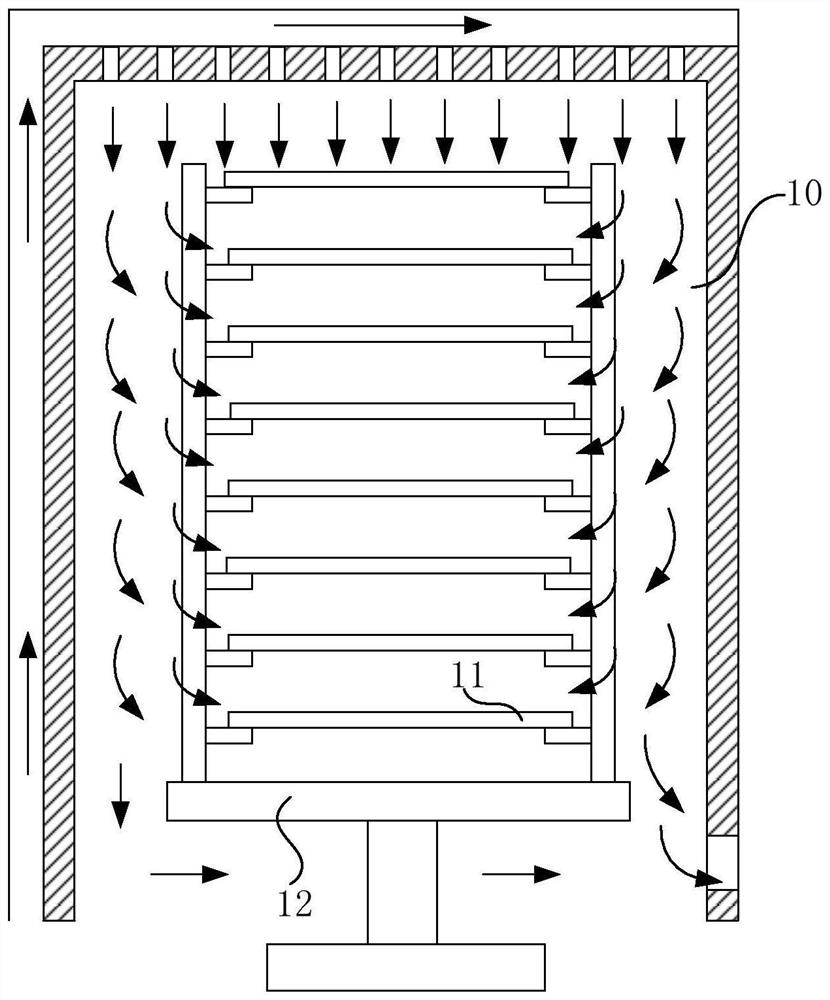
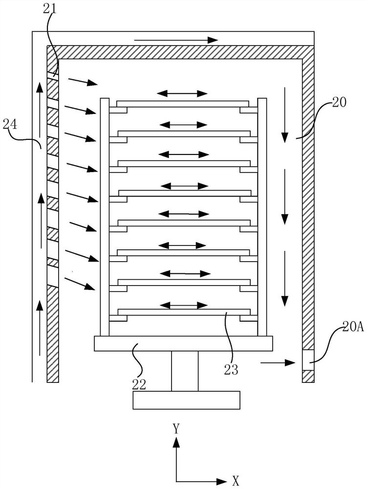
[0030] figure 2 It is a structural schematic diagram of the diffusion furnace of the first embodiment of the present invention. see figure 2 , the diffusion furnace includes a reaction chamber 20 and a plurality of gas pipelines 21 .

[0031] The reaction chamber 20 is used as a reaction chamber, and a wafer can be placed in the reaction chamber 20 to perform processes such as film deposition. Further, the diffusion furnace further includes a wafer boat 22 which can go deep into the reaction chamber 20 and carry a wafer 23 so as to place the wafer 23 in the reaction chamber 20 . Wherein, the wafer boat 22 can rotate to drive the wafer 23 to rotate in the reaction chamber 20 to achieve uniform deposition of reaction gas.

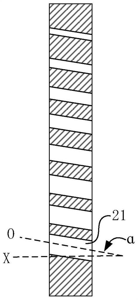
[0032] The reaction chamber 20 extends along a first direction. Such as f...


PUM

PropertyMeasurementUnit
lengthaaaaaaaaaa

Abstract

The present invention provides a diffusion furnace, comprising: a reaction chamber extending along a first direction, the reaction chamber having an exhaust end, a plurality of wafers capable of being sequentially arranged along the first direction, the surfaces of the wafers extending along a second direction, the second direction being perpendicular to the first direction or forming an acute angle with the first direction; the gas pipelines penetrate through the side wall of the reaction chamber so as to introduce external reaction gas into the reaction chamber, the gas channels are distributed from the exhaust end in the first direction, and an acute included angle is formed between the axis of each gas channel and the second direction. The reaction gas sprayed from the gas channel can directly reach the center of the wafer through the inclined design of the gas channel, so that the problem that the two sides are thick and the middle is thin in the deposition process is solved, due to the exhaust effect of the exhaust end, the reaction gas reaches the middle of the wafer and diffuses towards the two sides, meanwhile, diffusion of the gas is accelerated through rotation of the wafer boat, and the deposition efficiency is improved. Therefore, the thickness of the film layer deposited at the center and the edge of the surface of the single wafer is more uniform, and the product yield is improved.

Description

technical field [0001] The invention relates to the field of semiconductor manufacturing, in particular to a diffusion furnace. Background technique [0002] Diffusion furnace is one of the important process equipment in the pre-process of semiconductor production line. It is used for diffusion, oxidation, annealing, alloying and sintering processes in industries such as large-scale integrated circuits, discrete devices, power electronics, optoelectronic devices and optical fibers. [0003] figure 1 is a schematic diagram of an existing diffusion furnace, see figure 1 , the diffusion furnace has a reaction chamber 10 , and a wafer 11 is placed on a wafer boat 12 and placed in the reaction chamber 10 . When carrying out process deposition, reaction gas sprays from the top of described reaction chamber 10, and diffuses to wafer 11 surface (for the diffusion route of reaction gas, please refer to figure 1 Indicated by the middle arrow) for deposition. The disadvantage of th...

Claims


Application Information

Patent Timeline
Patent Type & Authority Applications(China)
IPC IPC(8): C23C16/455C23C16/458C23C16/52
CPCC23C16/455C23C16/4581C23C16/52C23C16/458H01L21/22H01L21/02Y02P70/50
Inventor 崔征
Owner CHANGXIN MEMORY TECH INC
Why Eureka
Try Eureka