Novel speed reducer

A reducer, a new type of technology, applied in the direction of transmission, toothed components, gear lubrication/cooling, etc., can solve the problems of box cracking, affecting service life and working reliability, bearing damage, etc., to reduce weight and Occupies space, improves work adaptability, and is easy to produce and install

Pending Publication Date: 2022-04-22
东方智造(西安)传动科技有限公司
View PDF0 Cites 0 Cited by
  • Summary
  • Abstract
  • Description
  • Claims
  • Application Information

AI Technical Summary

Problems solved by technology

[0004] 1) The motor is generally started with load, and the instantaneous input power of the motor is large, which often leads to broken shafts;
[0005] 2) When the steamer and steamer are working off-line, a heating device needs to be equipped. Due to the lack of a reasonable cooling device, the working temperature of the transmission shaft, bearings, seals, and oil seals is often too high, which affects their service life and work reliability;
[0006] 3) The reducer is generally installed vertically. The oil level of the lubricating oil in the box needs to be within a reasonable range. The user is required to check frequently and regularly during use. A little carelessness will cause the reducer to lack oil, and the side and top bearings will be damaged. Carry out dry grinding, resulting in frequent occurrence of bearing damage, gear grinding, and box cracking;
[0007] 4) The working environment of the reducer is complicated, and the box body cannot guarantee that its working ground is firm and flat during installation
Because the foundation surface is uneven and not strong, the reducer often swings up and down, left and right during operation, causing the reducer, the motor, and the load shaft of the equipment to be out of concentricity, and the situation of suffocation, jamming, and motor burnout often occurs.

Method used


Image

  • Novel speed reducer
  • Novel speed reducer
  • Novel speed reducer

Examples


Embodiment Construction

[0041] In describing the present invention, it should be understood that relational terms such as first and second etc. are only used to distinguish one entity or operation from another entity or operation and do not necessarily require or imply that these entities or operations, any such actual relationship or order exists. Furthermore, the term "comprises", "comprises" or any other variation thereof is intended to cover a non-exclusive inclusion such that a process, method, article or apparatus comprising a set of elements includes not only those elements, but also includes elements not expressly listed. other elements of or also include elements inherent in such a process, method, article, or device. Also, the terms "center", "upper", "lower", "front", "rear", "left", "right", "vertical", "horizontal", "top", "bottom", "inner ", "outside" and other indicated orientations or positional relationships are based on the orientations or positional relationships shown in the draw...


PUM


Abstract

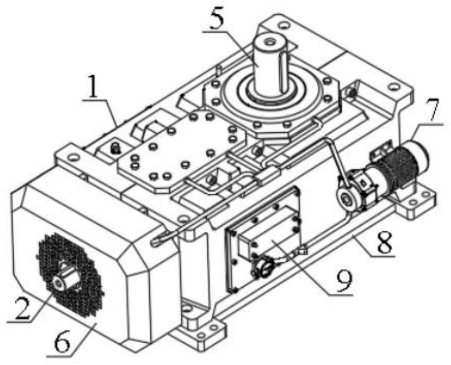
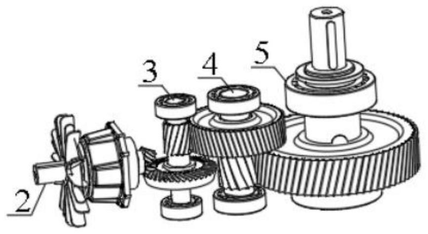
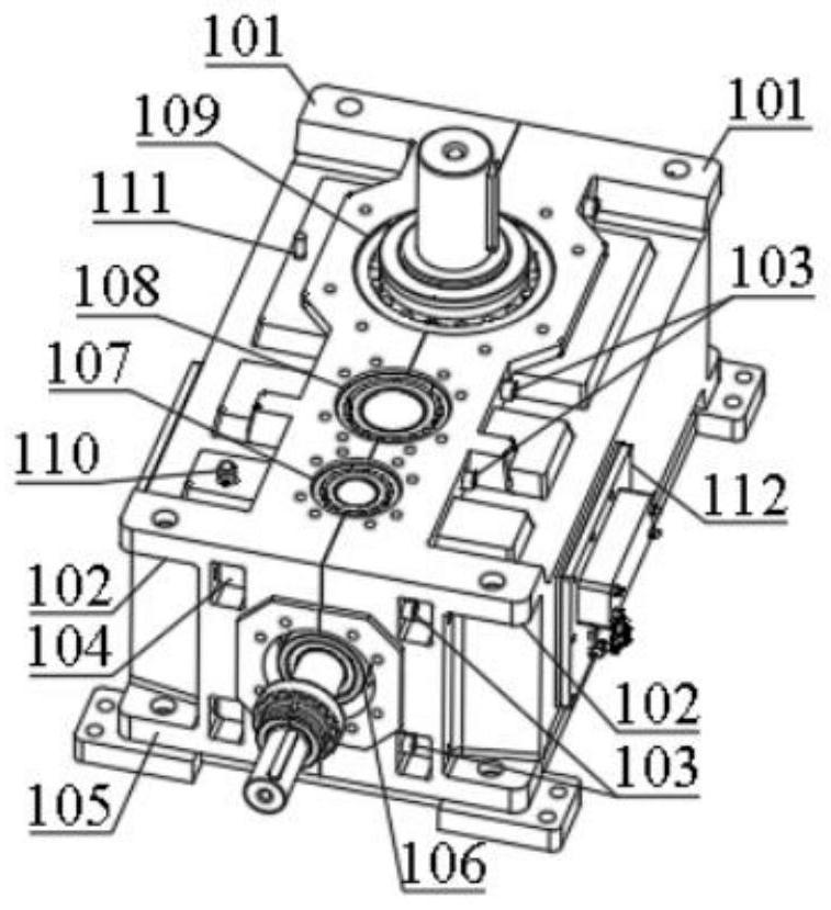
The invention provides a novel speed reducer, which belongs to special mechanical equipment, and comprises a box body, an input structure, a first-stage transmission structure, a second-stage transmission structure, an output structure, an air cooling device, a lubricating device, a flat base plate and the like, the first-stage transmission structure, the second-stage transmission structure and the output structure are vertically mounted in the box body side by side, and the input structure and the first-stage transmission structure are in transmission through a bevel gear set; cylindrical gear set transmission is adopted between the first-stage transmission structure and the second-stage transmission structure and between the second-stage transmission structure and the output structure. Compared with the prior art, the speed reducer is reasonable in structure and high in load capacity, the fan impeller of the air cooling device is directly arranged on the input shaft in a sleeving mode, heat transfer of the input shaft is greatly reduced, in addition, the arranged lubricating device can continue to lubricate the gear and the bearing under the condition that the oil level is low, and the speed reducer is particularly suitable for steaming and frying pans and evapo-separated machines in the grease industry.

Description

technical field [0001] The invention relates to a new speed reducer, which belongs to special mechanical equipment. Background technique [0002] The reducer is an independent component composed of gear transmission, worm transmission, and gear-worm transmission enclosed in a rigid shell. It is often used as a reduction transmission device between the original moving part and the working machine. It plays the role of matching speed and transmitting torque between prime mover and working machine or actuator, and is widely used in modern machinery. [0003] In the oil industry, equipment such as steaming woks and steaming machines also need to be equipped with reducers to achieve the technical effect of reducing speed and increasing torque. Conditions, there are the following technical defects: [0004] 1) The motor is generally started with load, and the instantaneous input power of the motor is large, which often leads to broken shafts; [0005] 2) When the steamer and st...

Claims


Application Information

Patent Timeline
Patent Type & Authority Applications(China)
IPC IPC(8): F16H1/20F16H57/02F16H57/025F16H57/027F16H57/028F16H57/029F16H57/032F16H57/038F16H57/04
CPCF16H1/203F16H57/02F16H57/025F16H57/027F16H57/028F16H57/029F16H57/032F16H57/038F16H57/0401F16H57/0404F16H57/0416F16H57/0417F16H57/0436F16H57/0441F16H57/0495F16H2057/02069F16H2057/02091
Inventor 赵琳娜赵俊皓
Owner 东方智造(西安)传动科技有限公司
Why Eureka
Try Eureka