
Distributed fiber Bragg grating sensor measurement and control system

A technology of Bragg gratings and distributed optical fibers, which is applied in the direction of converting sensor output, using optical devices to transmit sensing components, instruments, etc., can solve the problems of power fluctuations, the influence of power ratios of adjacent channels, and large differences in output optical power. Poor reliability, small size, and the effect of meeting high-bandwidth data transmission

Pending Publication Date: 2022-04-22
ZHEJIANG LAB
View PDF13 Cites 1 Cited by
  • Summary
  • Abstract
  • Description
  • Claims
  • Application Information

AI Technical Summary

Problems solved by technology

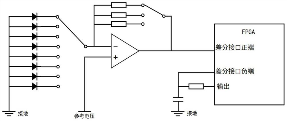
[0004] In order to solve the problem that the fiber grating demodulation chip based on arrayed waveguide grating has a large difference in the output optical power of adjacent channels in a dynamic environment, and the power fluctuation caused by noise has a significant impact on the power ratio of adjacent channels. Noise current / voltage conversion circuit and distributed fiber Bragg grating sensor measurement and control system of FPGA main control chip, improve the accuracy of the optical power ratio of adjacent channels, and realize a hybrid on-chip integrated fiber Bragg grating demodulation system

Method used


Image

  • Distributed fiber Bragg grating sensor measurement and control system
  • Distributed fiber Bragg grating sensor measurement and control system
  • Distributed fiber Bragg grating sensor measurement and control system

Examples


Embodiment Construction

[0031] The present invention will be further described below in conjunction with the accompanying drawings and specific implementation.

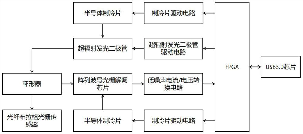
[0032] Such as figure 1 As shown, the system includes a fiber Bragg grating, a circulator, an arrayed waveguide grating demodulation chip, two semiconductor cooling chips, a cooling chip driving circuit, a low-noise current-voltage conversion circuit, FPGA, a superluminescent light-emitting diode and a superluminescent light-emitting diode driving circuit ; The FPGA is connected to the super-luminescent light-emitting diode through the super-radiant light-emitting diode driving circuit, and the FPGA is connected to the first semiconductor refrigerating plate through a refrigerating chip driving circuit, and the first semiconductor refrigerating chip is arranged on the super-radiating light-emitting diode; The chip driving circuit is connected with the second semiconductor cooling chip, and the second semiconductor cooling chip is arranged on...


PUM


Abstract

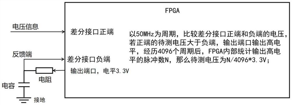
The invention discloses a distributed fiber bragg grating sensor measurement and control system. The FPGA is connected with the super-radiation light-emitting diode through the super-radiation light-emitting diode driving circuit, the FPGA is connected with the semiconductor chilling plates through the chilling plate driving circuit, the FPGA is connected with the semiconductor chilling plates through the chilling plate driving circuit, and the two semiconductor chilling plates are arranged on the super-radiation light-emitting diode and the array waveguide grating demodulation chip. The array waveguide grating demodulation chip is connected with the FPGA through the low-noise current and voltage conversion circuit; the super-radiation light-emitting diode emits light to the distributed fiber bragg grating sensor, and a light signal is reflected and enters the array waveguide grating demodulation chip. According to the invention, the signal-to-noise ratio is improved by changing the current / voltage conversion gain of the trans-impedance amplifier, the acquisition of the voltage signal is realized through the FPGA differential pin, the application complexity of the circuit is reduced without the help of an external voltage conversion chip, and the accuracy of the optical power ratio of adjacent channels is improved.

Description

technical field [0001] The invention relates to a grating measurement and control system, in particular to a distributed Bragg optical fiber grating measurement and control system in the field of photon integrated demodulators for distributed optical fiber sensing. Background technique [0002] Fiber Bragg Grating (FBG) sensors have many advantages over traditional electronic sensors in terms of compactness, immunity to electromagnetic interference, resistance to harsh environments, and multiplexing capabilities. The design and preparation of fiber Bragg gratings are relatively mature, and the main problem that limits the further wide application of fiber Bragg grating sensors is the demodulation of sensing signals. In current engineering applications, traditional fiber grating demodulators generally have disadvantages such as large volume and high cost, which seriously limit their popularization and application. For the evaluation of physiological indicators or in aerospac...

Claims


Application Information

Patent Timeline
Patent Type & Authority Applications(China)
IPC IPC(8): G01D5/26G01B11/16
CPCG01D5/268G01B11/165
Inventor 杨青张基强庄圆张璐王立强李燊
Owner ZHEJIANG LAB
Learn More