Protection device with low residual voltage

A protection device, low residual voltage technology, applied in emergency protection circuit devices for limiting overcurrent/overvoltage, emergency protection circuit devices, electrical components, etc. Limitation and other issues, to reduce the possibility of damage and fracture, ensure the effect of use, and ensure the effect of stability

Active Publication Date: 2022-04-22
苏州达晶微电子有限公司
View PDF13 Cites 0 Cited by
  • Summary
  • Abstract
  • Description
  • Claims
  • Application Information

AI Technical Summary

Problems solved by technology

[0004] Chinese patent document (CN11129366A) discloses a low residual voltage protection device for busbars used in power transmission and transformation systems. , the miniaturization of switchgear design, and the large number of applications of power cables put forward new requirements for insulation coordination and overvoltage protection. With the expansion of power supply system and the use of a large number of vacuum circuit breakers, the frequency of overvoltage is gradually increasing. If there are no preventive measures, the impact of overvoltage may occur at any time and the insulation of the electrical equipment in the system will be clamped and aged, causing insulation breakdown of the electrical equipment in the system.
The low residual voltage protection device of the busbar is generally installed in the protection cabinet for protection. The existing protection device cabinet is fixed on the ground. The connection contact port is loose, so that the protection device will not be able to work normally, and it needs to be improved to meet the needs of use.” At the same time, it is pointed out in the manual that “when the cabinet in this device has shocks such as vibrations outside the ground, the vibrations will be transmitted to the installation plate. On the top, the mounting plate is transferred to the first slider and the second slider, and the first slider and the second slider are pressed against the first support plate and the second support plate and are guided by the inclined plane, thereby pressing to both sides Move, the first slider and the second slider squeeze the first spring and the second spring, absorb the vibration energy through the first spring and the second spring, reduce the vibration impact, so as to absorb the vibration of the cabinet and keep the inside of the cabinet The line connection is reliable, which improves the stable operation of the device; the cabinet body can be further damped by the third spring, and the up and down shock absorption effect can be improved; the elastic support mechanism between the first fixed block and the second fixed block can prevent lateral vibration Further slow down and improve the effect of lateral shock absorption; the elastic support mechanism contacts the second fixed block through the roller to prevent the device from being stuck. However, in actual operation and application, it cannot completely solve the problem between the busbar and the protection device The stability of the connection, which still has the problem of shaking and high temperature, therefore in the existing protection device and the device described in the cited comparative case, the following problems still exist:
[0005]1. In order to ensure the stability of the installation, most of the current protection devices are installed and fixed by opening holes on the ground or walls. After installation, due to the closeness to the wall, the heat dissipation surface is limited, and the high temperature emitted by the internal components during operation is difficult to quickly discharge, which makes it difficult to guarantee the stability of the protection device itself, and is prone to high temperature damage.
[0006]2. At present, after the protection device is fixed by bolts, springs and other auxiliary devices are used to protect and buffer it in some occasions. After the connection with the protective device is completed, the connection will be dislocated with the overall shaking of the protective device. At the same time, with the continuous shaking of the protective device, the gap between the protective device connected to the bus bar will gradually expand, resulting in the contact between the bus bar and the protective device. The parts are prone to breakage and damage, which greatly limits the service life of protection devices and busbars, and is prone to short circuits

Method used


Image

  • Protection device with low residual voltage
  • Protection device with low residual voltage
  • Protection device with low residual voltage

Examples


Embodiment Construction

[0032] The following will clearly and completely describe the technical solutions in the embodiments of the present invention with reference to the accompanying drawings in the embodiments of the present invention. Obviously, the described embodiments are only some of the embodiments of the present invention, not all of them. Based on the embodiments of the present invention, all other embodiments obtained by persons of ordinary skill in the art without making creative efforts belong to the protection scope of the present invention.

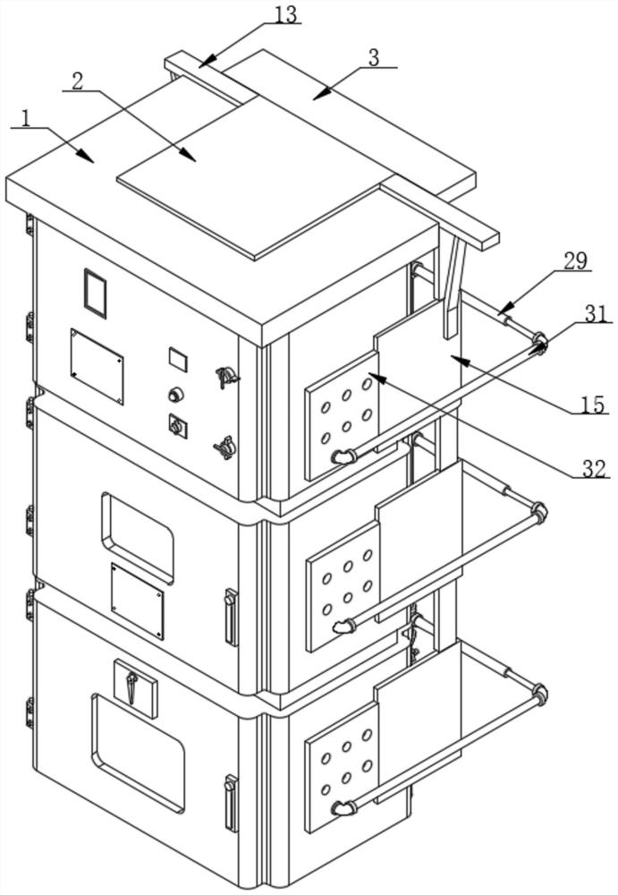
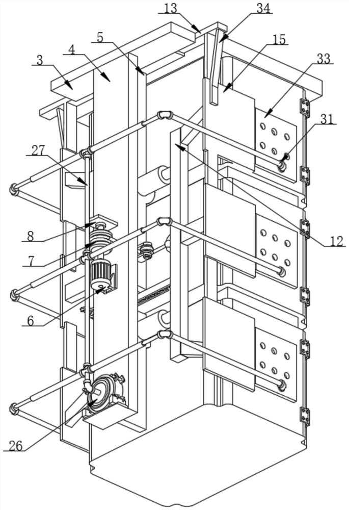
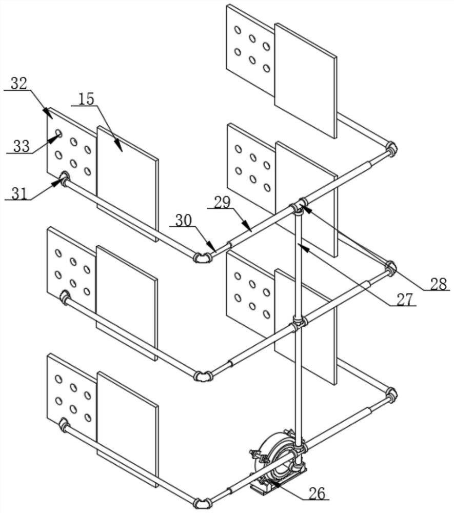
[0033] Such as Figure 1-7 As shown, the present invention provides a low residual voltage protection device, including a residual voltage protection device 1, the upper surface of the residual voltage protection device 1 is overlapped with the lower surface of the top pressure plate 2, and the upper surface of the residual voltage protection device 1 is opened There is a positioning groove, the top pressing plate 2 is located in the positioning ...


PUM


Abstract

The invention discloses a low-residual-voltage protection device, and particularly relates to the technical field of power transmission protection devices, the low-residual-voltage protection device comprises a residual-voltage protection device, the upper surface of the residual-voltage protection device is in lap joint with the lower surface of a top pressing plate, and a positioning groove is formed in the upper surface of the residual-voltage protection device; the top pressing plate is located in a positioning groove formed in the upper surface of the residual voltage protection device. According to the residual voltage protection device, by arranging the positioning toothed plates, the winding cable and the side pressing plate, after positioning is completed, the two positioning toothed plates fix the position of the side plate, meanwhile, the driving device can fix the driving shaft through internal parts of the driving device, and therefore the stability of the side pressing plate when the residual voltage protection device is fixed is guaranteed, and in the actual use process, the residual voltage protection device can be fixed more stably. The condition that the connecting part of the residual voltage protection device and the bus is loosened and falls off due to shaking after the residual voltage protection device is installed is avoided, it is guaranteed that the residual voltage protection device is not prone to short circuit in the using process, and the actual using effect of the protection device is guaranteed.

Description

technical field [0001] The invention relates to the technical field of power transmission protection devices, and more specifically, the invention relates to a protection device with low residual voltage. Background technique [0002] With the continuous advancement of science and technology, the battery life of consumer electronic products has attracted more and more attention from consumers, and the longer the battery life, the problem that comes with it is the extension of charging time. To achieve fast charging, then charging The current must be increased, and the output voltage must be increased accordingly. At present, the charging terminal voltage of most electronic products is increased from the original 5V to 9V or 12V, and the charging current is increased to 2A, 2.5A, etc. In the actual application process, the plugging action during charging, external static electricity, and transient glitch voltage or surge voltage generated in the circuit system may cause irrev...

Claims


Application Information

Patent Timeline
Patent Type & Authority Applications(China)
IPC IPC(8): H02H9/04H05K7/20
CPCH02H9/04H02H9/044H05K7/20136H05K7/20145Y02E10/72
Inventor 廖兵
Owner 苏州达晶微电子有限公司
Why Eureka
Try Eureka