Ultraviolet light response self-assembly synergistic dielectrophoresis polishing method and device
A polishing device and ultraviolet light technology, which is applied in the direction of surface polishing machine tools, grinding/polishing equipment, metal processing equipment, etc., can solve the problems of low material removal rate, inhomogeneity of polished complex curved surface, and poor adaptability of workpiece surface Improve the material removal rate, good workpiece surface uniformity, and good reversibility
- Summary
- Abstract
- Description
- Claims
- Application Information
AI Technical Summary
Problems solved by technology
Method used
Image

Examples
Embodiment Construction
[0050] The present invention will be further described below in conjunction with accompanying drawing:
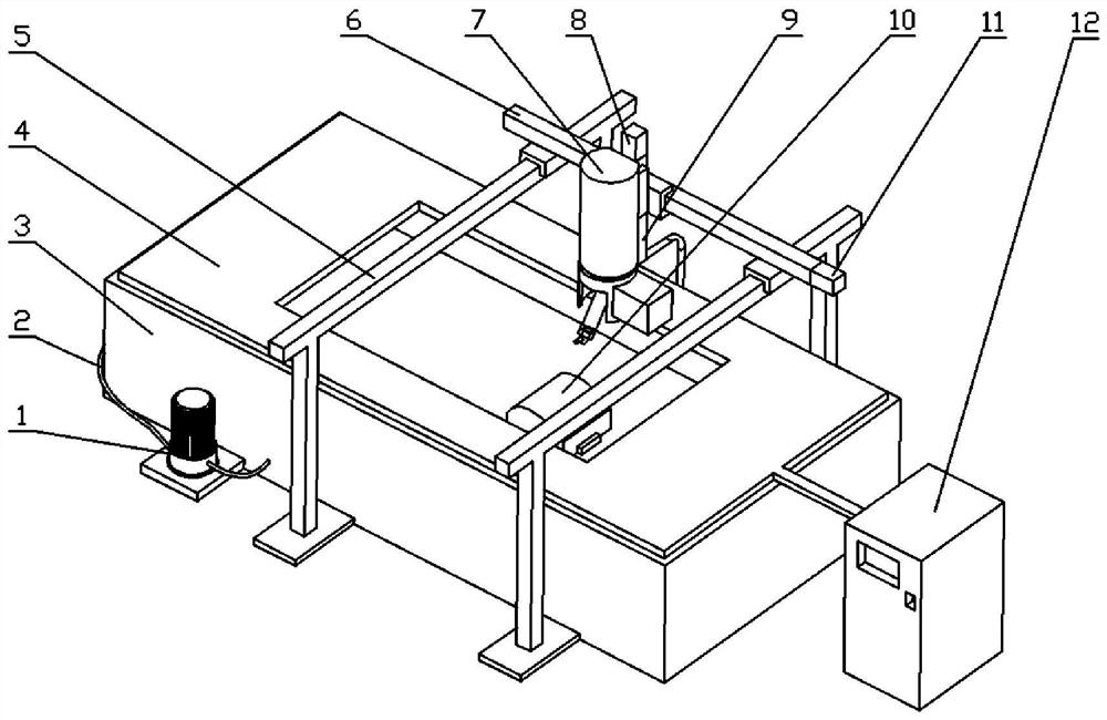
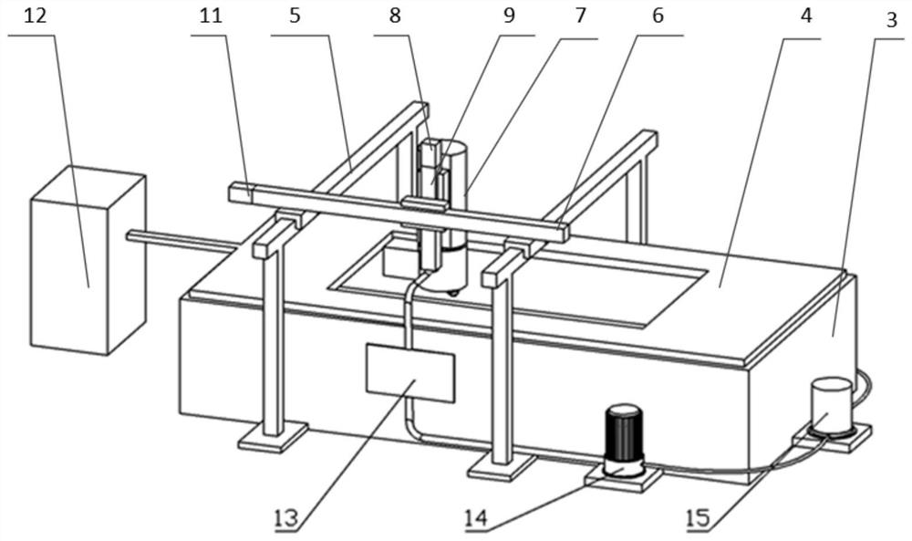
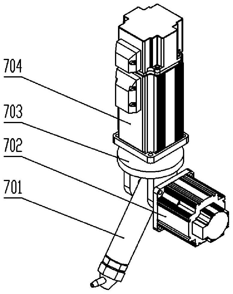
[0051] Such as Figure 1-10 Shown = a submersible polishing device based on an ultraviolet light response self-assembly system, including a first polishing liquid delivery pump 1, a polishing liquid delivery pipe 2, a second polishing liquid delivery pump 14, a polishing box 3, and a polishing box upper cover 4. Y-axis linear module 5, X-axis linear module 6, Z-axis linear module 9, tool device 7, workpiece to be polished 10, Y-axis servo motor 11, X-axis drive motor, Z-axis drive motor 8, cavity Inner light source, light control device 12, viscosity-adjusting thin fluid layer 13 and stirring device 15, the polishing box 3 and the polishing box upper cover 4 are fixedly connected, and the polishing box 3 and the polishing box upper cover 4 together constitute a polishing body The polishing chamber, the polishing body is placed in the polishing chamber, the middle part of t...
PUM
 Abstract
Description
Claims
Application Information
 - R&D
- Intellectual Property
- Life Sciences
- Materials
- Tech Scout
- Unparalleled Data Quality
- Higher Quality Content
- 60% Fewer Hallucinations
Browse by: Latest US Patents, China's latest patents, Technical Efficacy Thesaurus, Application Domain, Technology Topic, Popular Technical Reports.
© 2025 PatSnap. All rights reserved.Legal|Privacy policy|Modern Slavery Act Transparency Statement|Sitemap|About US| Contact US: help@patsnap.com