Improved low-energy-consumption CO2 stripping method urea process

A steam stripping and low energy consumption technology, applied in the field of urea technology, can solve the problems of consumption of circulating water, insufficient energy recovery, and impact on energy saving effect, and achieve the goals of reducing medium pressure steam consumption, increasing synthesis conversion rate, and saving steam consumption Effect

Pending Publication Date: 2022-04-29
WUHUAN ENG
View PDF13 Cites 0 Cited by
  • Summary
  • Abstract
  • Description
  • Claims
  • Application Information

AI Technical Summary

Problems solved by technology

However, there are the following problems: (1) high-pressure CO 2 The liquid phase of the stripper and the medium pressure CO 2 The liquid phase of the stripping tower is sent to the low-pressure decomposition tower together, and no medium-pressure decomposition and recovery is carried out. On the one hand, this will lead to a large amount of water returned to the high-pressure ring, and the ammonia-to-carbon ratio in the high-pressure ring is relatively high, which is unfavorable to the urea reaction and affects to a certain extent On the other hand, the load of low-pressure decomposition and recovery will be heavy, which is not conducive to further shifting the load of the high-pressure stripper, resulting in limited expansion capacity or limited energy-saving effect; (2) the medium-pressure carbamate condenser The heat of reaction is directly taken away by circulating water. On the one hand, high-quality low-temperature heat is wasted, and on the other hand, more circulating water is consumed, resulting in insufficient energy recovery and high operating costs.

Method used


Image

  • Improved low-energy-consumption CO2 stripping method urea process

Examples


Embodiment Construction

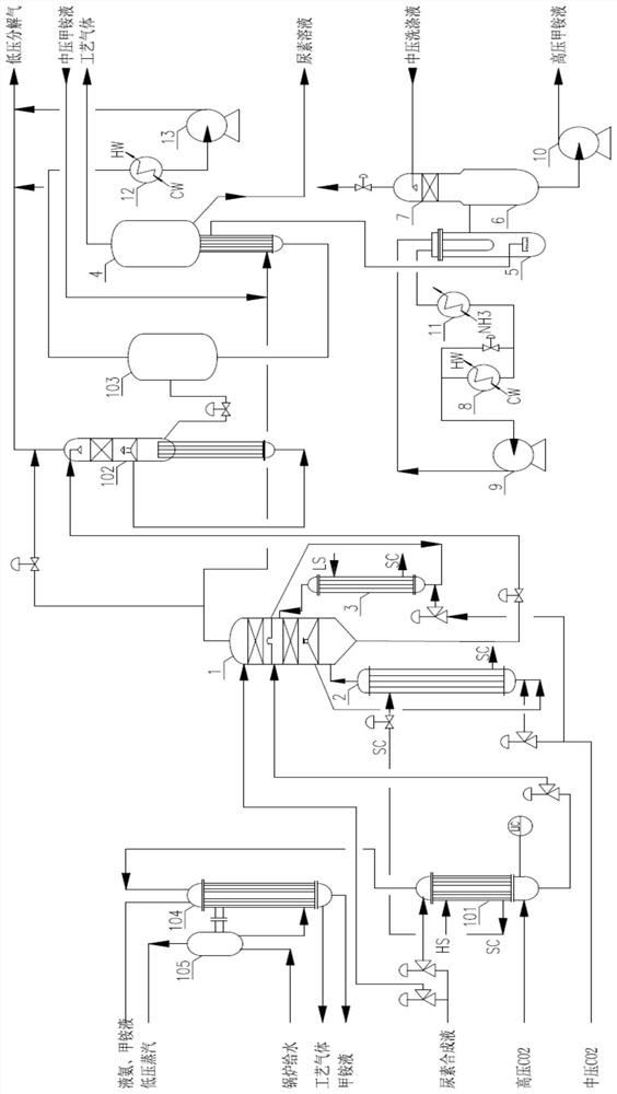
[0023] Below in conjunction with accompanying drawing, the present invention will be further explained:

[0024] see figure 1 , the urea synthesis solution containing methylammonium coming out from the bottom of the urea synthesis tower, the urea concentration is 33.6%wt, and the temperature is 183°C.

[0025]The urea synthesis solution is divided into two parts, and a part of the urea synthesis solution (55-99wt% of the total amount) is sent to the high-pressure CO decomposition recovery system. 2 High pressure CO in the stripper 101 2 Stripping, high pressure CO 2 The stripping gas discharged from the top of the stripping tower 101 is sent to the high-pressure methylammonium condenser 104 to condense and recover the methylammonium liquid, and discharge the methylammonium liquid and uncondensed process gas. steam to recover heat energy;

[0026] Another part of the urea synthesis liquid (1-45wt% of the total amount) is decompressed and sent to the upper section of the med...


PUM


Abstract

According to the technical scheme, urea synthesis liquid is divided into two parts, one part of urea synthesis liquid is fed into a high-pressure CO2 stripping tower in a high-pressure decomposition and recovery system to be subjected to high-pressure CO2 stripping, and the other part of urea synthesis liquid is fed into a high-pressure CO2 stripping tower in a high-pressure decomposition and recovery system to be subjected to high-pressure CO2 stripping; the other part of the urea synthesis liquid is fed into a medium-pressure decomposition tower of the medium-pressure decomposition recovery system for medium-pressure decomposition, and a medium-pressure gas phase and a medium-pressure decomposition liquid phase are obtained. High-pressure stripping liquid flowing out of the bottom of the high-pressure CO2 stripping tower and the other part of urea synthesis liquid are decompressed and then are respectively fed into the middle section and the upper section of a medium-pressure decomposition tower for medium-pressure gas-liquid separation, and medium-pressure decomposition liquid led out of the bottom of the medium-pressure decomposition tower is fed into a low-pressure decomposition tower for low-pressure decomposition. The method is simple in process, easy to transform, capable of further saving energy and reducing consumption, capable of improving productivity and low in investment and operation cost.

Description

technical field [0001] The invention relates to a urea process, in particular to an improved low-energy CO 2 Stripping urea process. Background technique [0002] Industrial urea production is based on CO 2 Gas and liquid ammonia are used as raw materials, which are processed into solid urea products through high-pressure synthesis, medium-pressure or / and low-pressure decomposition and recovery, vacuum concentration, and granulation. [0003] At present, the production process of urea plant at home and abroad mainly includes the CO produced by Stamicarbon in the Netherlands. 2 Steam stripping process, Italian Snamprogetti ammonia stripping process, Japan TOYO's ACES21 process, China's five-ring high-efficiency synthesis, low-energy urea process, aqueous solution method full cycle process, etc., among which CO 2 The stripping process and the ammonia stripping process are the most competitive. [0004] Traditional CO 2 The process flow of the stripping method is that the ...

Claims


Application Information

Patent Timeline
Patent Type & Authority Applications(China)
IPC IPC(8): C07C273/04C07C273/16C07C275/00F22D1/00
CPCC07C273/04C07C273/16F22D1/00C07C275/00Y02P20/141
Inventor 夏炎华杨志国孙喜望姣赟余志文
Owner WUHUAN ENG
Why Eureka
Try Eureka