
Electric equipment power supply frequency abnormity detection circuit and method

A technology of power supply frequency and electrical equipment, which is applied in the field of abnormal power supply frequency detection circuit of electrical equipment, which can solve problems such as production line stoppage and equipment falsely reporting abnormal power supply frequency, so as to improve accuracy and avoid false alarm of abnormal power supply frequency Effect

Pending Publication Date: 2022-04-29
GREE ELECTRIC APPLIANCES INC
View PDF0 Cites 1 Cited by
  • Summary
  • Abstract
  • Description
  • Claims
  • Application Information

AI Technical Summary

Problems solved by technology

[0004] The embodiment of the present invention provides a circuit and method for detecting abnormal power supply frequency of electrical equipment to solve the problem in the prior art that interference spikes cause equipment to falsely report abnormal power supply frequency, which in turn leads to unnecessary shutdown of the entire production line

Method used


Image

  • Electric equipment power supply frequency abnormity detection circuit and method
  • Electric equipment power supply frequency abnormity detection circuit and method
  • Electric equipment power supply frequency abnormity detection circuit and method

Examples


Embodiment 1

[0061] This embodiment provides a circuit for detecting abnormal power supply frequency of electrical equipment, figure 1 It is a structural block diagram of a power supply frequency abnormal detection circuit for electrical equipment according to an embodiment of the present invention, as shown in figure 1 As shown, the abnormal detection circuit of the power supply frequency of the above-mentioned electrical equipment includes:

[0062] The XOR logic module 10 is used to input the power supply frequency detection signal and a square wave signal with the same frequency and phase as the power supply frequency detection signal, and perform XOR logic processing to generate a sampling signal; wherein, the duty cycle of the above square wave signal is equal to the frequency The duty cycle of the power supply voltage at normal time, for example, if the duty cycle of the power supply voltage is 50% when the frequency is normal, the duty cycle of the above square wave signal is also ...

Embodiment 2

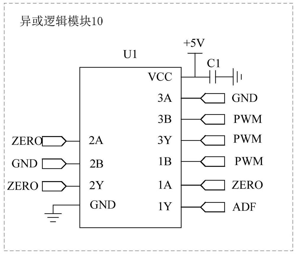
[0067] This embodiment provides another detection circuit for abnormal power supply frequency of electrical equipment, figure 2 is a structural diagram of an XOR logic module according to an embodiment of the present invention, such as figure 2 As shown, the XOR logic module includes:

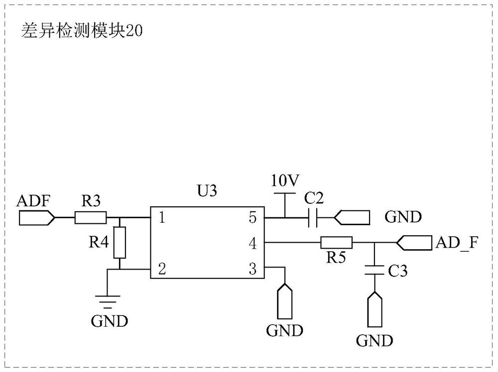
[0068] The exclusive OR gate chip U1, its first pin Vcc is connected to the first voltage source, one end of its second pin 1A inputs the power supply frequency detection signal ZERO, and the other end is connected to the first exclusive OR gate element inside the exclusive OR gate chip U1 ( not shown in the figure), one end of its third pin 1B inputs a square wave signal PWM, the other end is connected to the second input end of the first XOR gate element, and one end of its fourth pin 1Y is connected to The output end of the first XOR gate element, the other end is connected to the difference detection module 20 for outputting the sampling signal ADF, and its fifth pin GND is grounded; the...

Embodiment 3

[0078] This embodiment provides an electric device, including the above-mentioned abnormal power supply frequency detection circuit of the electric device. In a specific implementation, the electric device is an induction heating device.


PUM


Abstract

The invention discloses an electric equipment power supply frequency abnormity detection circuit and method. The circuit comprises an XOR logic module which is used for inputting a power supply frequency detection signal and a square wave signal with the same frequency and phase as the power supply frequency detection signal, and performing XOR logic processing to generate a sampling signal; wherein the duty ratio of the square wave signal is equal to the duty ratio of the power supply voltage when the frequency is normal; the input end of the difference detection module is connected with the XOR logic module, and the difference detection module is used for converting the sampling signal into a direct current signal and outputting the direct current signal to a digital signal processor; and the digital signal processor is used for judging whether the power supply frequency is abnormal or not according to the voltage value carried by the direct current signal. According to the invention, false alarm of power supply frequency abnormity caused by interference peaks can be avoided, and the accuracy of power supply frequency abnormity protection of electric equipment is improved.

Description

technical field [0001] The invention relates to the technical field of electronic power, in particular to a circuit and method for detecting abnormal power supply frequency of electric equipment. Background technique [0002] Most of the induction heating equipment in the factory adopts multiple equipment assembly line operations to form a product assembly line for the induction heating welding process. According to different welding workpieces and different processes, several induction heating equipment equipped with different induction coils are selected. Since one piece of equipment stops working, the entire product assembly line will stop, which requires that the operation stability of several induction heating equipment working together must be very high. There are many industrial-grade electrical equipment in the factory, with high power and high load, which leads to more harmonic interference in the power grid in the factory, poor power quality, and the electromagneti...

Claims


Application Information

Patent Timeline
Patent Type & Authority Applications(China)
IPC IPC(8): G01R31/08
CPCG01R31/08
Inventor 杨勇越黄猛姜颖异付鹏亮陈慢林
Owner GREE ELECTRIC APPLIANCES INC
Learn More