
Multi-station fusion comprehensive energy station carbon flow situation awareness and low-carbon operation method

A comprehensive energy and situational awareness technology, applied in the field of electric energy, can solve the problems of lack of energy flow and carbon emission flow monitoring research, and the inability to effectively analyze the key factors of energy efficiency and emission reduction of integrated energy stations, and achieve significant economic and social welfare benefits , Improve scale and operational efficiency, and reduce carbon emissions

Pending Publication Date: 2022-05-13
STATE GRID JIANGSU ECONOMIC RES INST
View PDF0 Cites 2 Cited by
  • Summary
  • Abstract
  • Description
  • Claims
  • Application Information

AI Technical Summary

Problems solved by technology

[0003] At present, research on carbon flow situational awareness is mostly at the macro level of the country, city, and industrial park. There is a lack of monitoring research on the energy flow and carbon emission flow of the primary energy, transformers, and various terminal equipment of the micro-scale multi-station integrated energy station. Effectively analyze the key factors affecting the energy efficiency of integrated energy stations and extracting emission reductions

Method used


Image

  • Multi-station fusion comprehensive energy station carbon flow situation awareness and low-carbon operation method
  • Multi-station fusion comprehensive energy station carbon flow situation awareness and low-carbon operation method
  • Multi-station fusion comprehensive energy station carbon flow situation awareness and low-carbon operation method

Examples


Embodiment

[0051] Choose February 11, 2021, with stronger solar irradiance. Collect photovoltaic output forecast and load forecast data every 15 minutes from 00:00am to 23:55pm. At 11:00 a.m., the photovoltaic output meets the load in the station, and the 5G communication station and data center modules run at full capacity. At this time, there is still a surplus of photovoltaic output, and the energy storage module enters the charging mode. The charging and discharging time of the energy storage module is adjusted according to the photovoltaic output and all in-station load forecasts, and the operation mode of the energy storage module is optimized. The carbon emission of the comprehensive energy station is 2915.67kg throughout the day. In contrast, carbon emissions were reduced by 23.13% when the PV was not working. Carbon emission distribution comparison chart Figure 5 shown.

[0052] Based on the energy flow-carbon flow theory, the present invention realizes the carbon flow situ...


PUM


Abstract

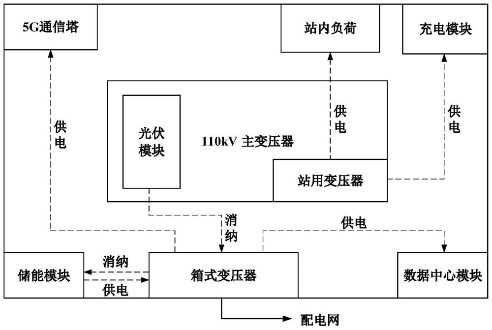
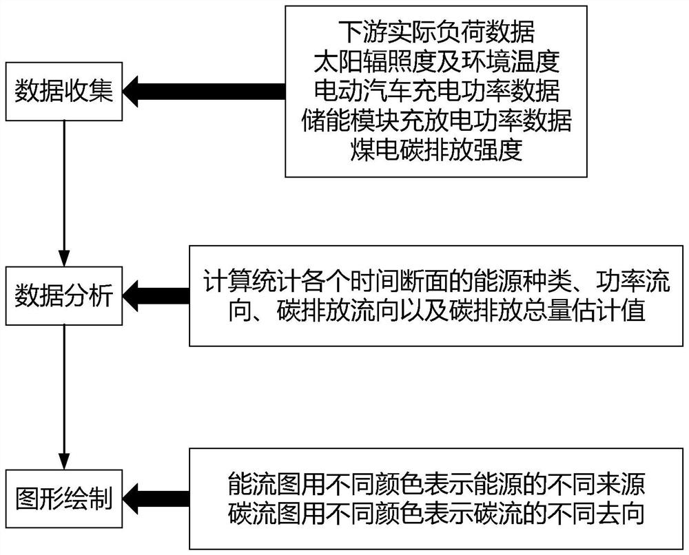
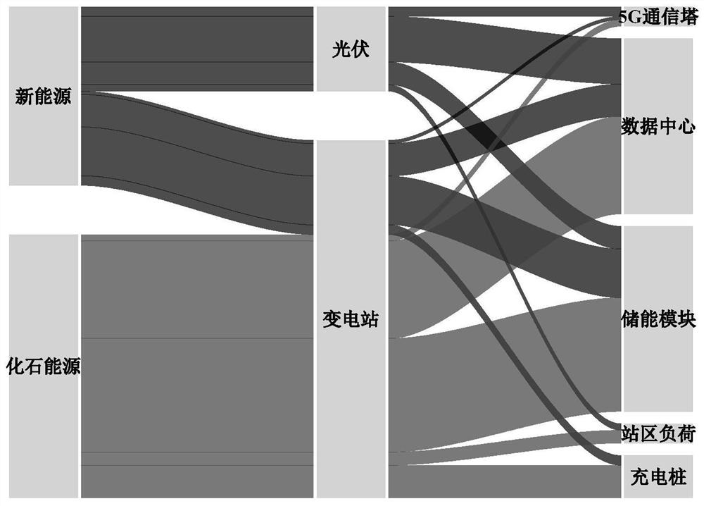
The invention discloses a carbon flow situation awareness and low-carbon operation method for a multi-station integrated comprehensive energy station, and belongs to the technical field of electric energy. The method comprises the following steps: firstly, determining a main body structure, capacity configuration, an arrangement form and a wiring mode of the comprehensive energy station based on a principle of maximum utilization and most efficient construction and function positioning; drawing an energy flow-carbon flow diagram, tracking a carbon source, and sensing a carbon flow situation; according to the load capacity and photovoltaic power generation characteristics of various facilities of the comprehensive energy station, energy flow and carbon flow information is analyzed, main factors influencing carbon emission are obtained, and a low-carbon optimization operation model is constructed. Real-time sensing and low-carbon operation of the carbon flow situation of the comprehensive energy station are achieved, the energy structure, the energy flow direction and the carbon flow information of the comprehensive energy station are visually displayed, and an energy conservation and emission reduction strategy is provided for operation of an existing comprehensive energy station and planning of a to-be-built comprehensive energy station.

Description

technical field [0001] The invention provides a multi-station fusion comprehensive energy station carbon flow situation awareness and low-carbon operation method, which belongs to the technical field of electric energy. Background technique [0002] In the process of achieving the goal of carbon peaking and carbon neutrality, the energy industry plays an important role and undertakes the important task of low-carbon transformation of national energy supply and consumption. The development of low-carbon electricity is the only way to achieve the goal of carbon reduction in the power industry. As a national strategic emerging industry, the integrated energy station is an important development direction of integrated energy services, and it is also an active attempt by the power industry to explore and achieve dual carbon targets. In 2020, the National Energy Administration will include integrated energy services into the national energy plan and encourage active exploration of...

Claims


Application Information

Patent Timeline
IPC IPC(8): G06Q10/04G06Q10/06G06Q50/06G06F30/20G06F111/04G06F113/04
CPCG06Q10/04G06Q10/06312G06Q10/06313G06Q50/06G06F30/20G06F2113/04G06F2111/04Y02E40/70Y04S10/50
Inventor 李妍汪德成张群潘学萍孙晓荣许一
Owner STATE GRID JIANGSU ECONOMIC RES INST
Learn More