Method for manufacturing real coal two-dimensional microfluid model

A manufacturing method and microfluidic technology, applied in teaching models, instruments, graphics and image conversion, etc., can solve problems such as failure to observe channel fluid flow, adsorption, diffusion, failure to achieve nanoscale microscopic models, and poor observation effects. , to achieve the effect of reducing human influence, ensuring consistency and simple use

Active Publication Date: 2022-05-13
CHINA UNIV OF MINING & TECH
View PDF14 Cites 0 Cited by
  • Summary
  • Abstract
  • Description
  • Claims
  • Application Information

AI Technical Summary

Problems solved by technology

[0003] As a pore-fracture dual medium, coal has strong heterogeneity, and the coal-rock fracture network is mainly used as a channel for gas-water migration in the process of coalbed methane development. The gas-liquid or liquid-liquid flow in the tunnel is different from the gas-liquid flow in the cracks to be studied in the field of coalbed methane, and the material used in the existing coal model is glass material, and the glass material is obtained through the existing wet engraving method. Etching and dry etching cannot reach the nanoscale level or the microscopic model made of real sandstone slices as raw materials. During the production process, adhesives need to be added to change the surface properties of the core, and the observation effect is poor, and the fluid inside the observation channel cannot be reached. The purpose of flow, adsorption, and diffusion, on the other hand, when making microscopic models, sandstone with well-developed pores is often selected, which has certain limitations. Microscopic models used in the petroleum industry in the past are not suitable for gas in pore-scale coal reservoirs. Therefore, it is necessary to design a method for making a real coal two-dimensional microfluidic model to solve the above problems

Method used


Image

  • Method for manufacturing real coal two-dimensional microfluid model
  • Method for manufacturing real coal two-dimensional microfluid model
  • Method for manufacturing real coal two-dimensional microfluid model

Examples


Embodiment Construction

[0026] The technical solutions in the examples of the present invention will be clearly and completely described below in conjunction with the drawings in the embodiments of the present invention.

[0027] Extract the fracture network:

[0028] Step 1, drill a columnar coal sample with a diameter of 2.5 cm in the block sample, and then use sandpaper to grind the columnar sample into a cylindrical sample of 2.5*5 cm;

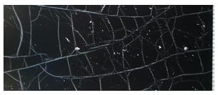
[0029] Step 2: Use alcohol to clean the cylindrical coal sample, and then place it in the CT scanning room for scanning to obtain a picture of the fracture network developed inside the sample, and then perform sharpening and noise reduction on the picture to obtain a higher quality fracture network picture.

[0030] Cut real coal samples:

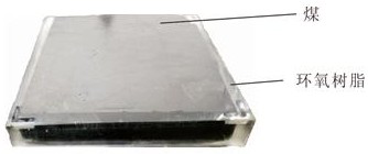
[0031] Step 1: Select a coal block of about 20*20*20 cm, and use a wire cutting machine to cut out a coal block with a size of 7.2*7.2*1.5 cm. It is required that the natural cracks on the surface of the coal block are not de...


PUM

PropertyMeasurementUnit
thicknessaaaaaaaaaa

Abstract

The invention provides a method for manufacturing a real coal two-dimensional microfluid model. The method comprises the following steps of: 1, scanning a columnar coal sample by using a CT (Computed Tomography) instrument to obtain a real fracture network; 2, a wire cutting machine is adopted, and blocky coal rock of 7.2 * 7.2 * 1.5 cm is cut on the large coal sample; 3, placing the real coal rock block on a silica gel grinding tool with the inner wall size of 8 cm * 8 cm * 2 cm, and pouring the epoxy resin glue until the epoxy resin glue is solidified; step 4, inputting the real fracture network or the simplified fracture into a laser marking machine, and etching the fracture on the surface of the blocky coal sample; and step 5, manufacturing a PET film of 7.2 * 7.2 cm, adding a silica gel coating with a nanometer thickness on one surface of the PET film through a coating process, and then bonding the PET film with the coal rock through the silica gel coating, so that the accuracy and controllability of the experiment are ensured, and the PET film and the nanometer silica gel coating have excellent light transmittance, so that the research on the basic theory of coal bed gas migration is facilitated. The method has important significance in improving the coal bed gas recovery ratio.

Description

technical field [0001] The invention designs the field of coal bed gas development, and in particular relates to a method for making a real coal two-dimensional microfluidic model. Background technique [0002] At present, with the continuous development of my country's coalbed methane industry, the continuous deepening of coalbed methane-related development theories, the mechanism of gas-water two-phase migration and the improvement of low-production well productivity have increasingly become research hotspots and difficulties; The research and development of the problem is mainly divided into two categories: real sandstone microscopic model and glass simulation model. [0003] As a pore-fracture dual medium, coal has strong heterogeneity, and the coal-rock fracture network is mainly used as a channel for gas-water migration in the process of coalbed methane development. The gas-liquid or liquid-liquid flow in the tunnel is different from the gas-liquid flow in the cracks t...

Claims


Application Information

Patent Timeline
Patent Type & Authority Applications(China)
IPC IPC(8): G09B25/00G06T3/00
CPCG09B25/00G06T3/005
Inventor 申建韩磊桑国蕴屈晶程慧杰李伟
Owner CHINA UNIV OF MINING & TECH
Why Eureka
Try Eureka