Die cutting process for single-sided high-hardness thick copper plate

A technology of high-hardness and thick copper plates, which is applied in the manufacture of printed circuits, electrical components, printed circuits, etc., can solve problems such as waste residues, inability to maintain the stability of single-sided high-hardness thick copper plates, end-face flatness, end-face warpage, etc., to achieve Maintain stability, facilitate centralized recycling and reuse, and avoid end face warping

Pending Publication Date: 2022-05-27
常州海弘电子有限公司
View PDF4 Cites 0 Cited by
  • Summary
  • Abstract
  • Description
  • Claims
  • Application Information

AI Technical Summary

Problems solved by technology

[0005] The purpose of the present invention is to provide a single-sided high-hardness thick copper plate die-cutting process, which is used to solve the problem that the stability of the single-sided high-hardness thick copper plate die-cutting process and the flatness of the end face after die-cutting cannot be maintained in the prior art, which is easy Technical issues causing end face warping and scrap residue

Method used


Image

  • Die cutting process for single-sided high-hardness thick copper plate
  • Die cutting process for single-sided high-hardness thick copper plate
  • Die cutting process for single-sided high-hardness thick copper plate

Examples


Embodiment 1

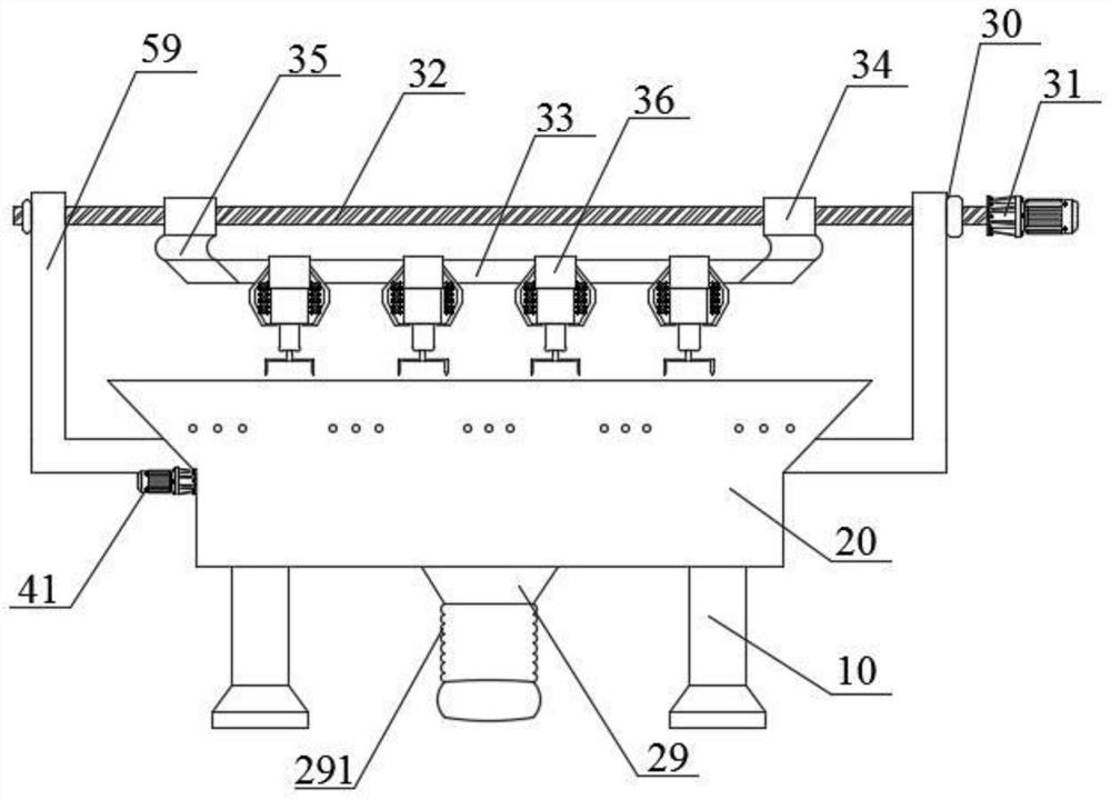
[0036] like Figure 1-3As shown, this embodiment provides a die-cutting device for a single-sided high-hardness thick copper plate, including a bracket 10, a mounting shell 20, and an adjustable die-cutting mechanism 30. The bracket 10 is arranged below the mounting shell 20, and can be The die-adjusting and cutting mechanism 30 is arranged above the installation casing 20, and the installation casing 20 is provided with a fixing device for limiting and fixing the single-sided high-hardness thick copper plate and performing end face milling on the single-sided high-hardness thick copper plate after die-cutting. Milling mechanism 40 . The die-cutting equipment performs adjustable die-cutting on a plurality of single-sided high-hardness thick copper plates through the adjustable die-cutting mechanism 30. The fixed milling and grinding mechanism 40 is limited and fixed during the die-cutting process, and end-face milling is performed after the die-cutting is completed. Maintain ...

Embodiment 2

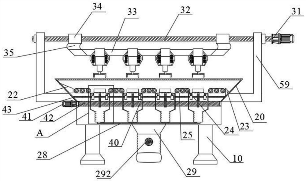
[0043] like Figure 2-3 , Figure 7 As shown, this embodiment provides a die-cutting equipment for single-sided high-hardness thick copper plates. The difference from Embodiment 1 is that a feeding table 22 is provided on one side of the inner cavity of the mounting shell 20, and the inner cavity is on the other side. A feeding table 23 is provided on one side. The inner cavity of the mounting shell 20 is located between the feeding table 22 and the die-cutting table 21 , between the adjacent die-cutting tables 21 , and between the die-cutting table 21 and the unloading table 23 , and there are multiple parallel roller sets. , the roller set consists of a plurality of parallel rollers 24 and a conveyor belt 25 wound around each roller 24 . The feeding table 22 is used for feeding the single-sided high-hardness thick copper plate, the roller set is used for conveying the single-sided high-hardness thick copper plate, and the unloading table 23 is used for unloading the single...

Embodiment 3

[0050] like Figure 1-7 As shown, this embodiment provides a single-sided high-hardness thick copper plate die-cutting process, which includes the following steps:

[0051] Step 1, after adding the single-sided high-hardness thick copper plate from the feeding table 22 of the die-cutting equipment, place a plurality of single-sided high-hardness thick copper plates in the accommodating groove 211 of the die-cutting table 21 through the roller set;

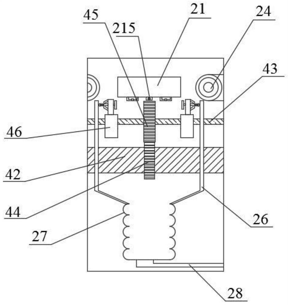
[0052] In step 2, the first reduction motor 41 drives the driving shaft 42 to rotate forward or reversely, the driving shaft 42 drives the driving gear 44 to rotate, and the driving gear 44 drives the driven gear 45 and the driven shaft 43 meshed with it to rotate, so that the limit milling is performed. The structure rotates to the lower sides of the die-cutting table 21; the second deceleration motor 31 drives the ball screw 32 to rotate, and the screw seat 34 meshing with the ball screw 32 drives the plurality of fixed tables 36...


PUM


Abstract

The invention discloses a die cutting process for a single-sided high-hardness thick copper plate, and relates to the technical field of copper plate cutting. According to the die cutting technology, automatic feeding, limiting and fixing, adjustable die cutting and end face milling and grinding are carried out through the die cutting equipment, the stability in the single-face high-hardness thick copper plate die cutting process and the end face smoothness after die cutting are kept, the end face warping and waste material residual conditions caused by die cutting are avoided, and the die cutting efficiency is improved through multi-station automatic die cutting; waste materials generated in the die cutting process of the multiple die cutting tables fall into the branch collecting bags and fall into the main collecting bag to be collected through the first corrugated pipe and the negative pressure pipe under the negative pressure effect generated by the negative pressure draught fan, centralized recycling and reusing are facilitated, and the clean environment of the interior of the installation shell and the surface of the single-face high-hardness thick copper plate is kept. The first corrugated pipe and the second corrugated pipe are good in elasticity and shake under the negative pressure effect in the collecting process, so that the waste materials are not prone to adhering to the inner walls of the branch collecting bags and the main collecting bag.

Description

technical field [0001] The invention relates to the technical field of copper plate cutting technology, in particular to a single-sided high-hardness thick copper plate die-cutting technology. Background technique [0002] Thick copper plate is a layer of copper foil bonded to the glass epoxy substrate of the printed circuit board. When the copper thickness is greater than or equal to 2oz, it is defined as a thick copper plate. Thick copper plate has good elongation performance and is not limited by processing temperature. Hot-melt welding methods such as oxygen blowing can be used when the melting point is high, and it is not brittle at low temperature. It is also fireproof and belongs to non-combustible materials. Copper plates form a strong, non-toxic passivation protective layer even in extremely corrosive atmospheres. [0003] The invention patent with the authorization announcement number CN112077937B discloses a copper clad laminate die-cutting processing equipment a...

Claims


Application Information

Patent Timeline
Patent Type & Authority Applications(China)
IPC IPC(8): B23P15/00H05K3/00
CPCB23P15/00H05K3/00Y02P70/10
Inventor 陈定红耿克非宦洪波
Owner 常州海弘电子有限公司
Why Eureka
Try Eureka