Ship lock type for silt-laden wandering river
A ship lock and sediment technology, which is applied in the field of ship lock types, can solve the problems of bank deposition, high labor intensity, insufficient water diversion depth, etc.
- Summary
- Abstract
- Description
- Claims
- Application Information
AI Technical Summary
Problems solved by technology
Method used
Image
Examples
Embodiment 1
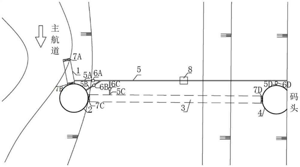
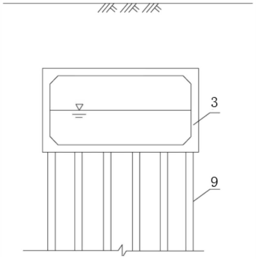
[0066] A type of lock for loitering rivers, such as figure 1 -2, including: entry channel 1, offshore ship lock 2, underground channel 3, docking ship lock 4 and a number of corresponding flushing drainage systems, between the entry channel 1 and the offshore ship lock 2, the offshore Several gates 7 are used for separation between the ship lock 2 and the underground channel 3 and between the underground channel 3 and the docking ship lock 4 . The lifting and lowering of the ship is realized through the flushing and drainage system. Preferably, both the offshore ship lock 2 and the berth ship lock 4 can be lift-and-turn type ship locks.
[0067] Preferably, both the offshore lock 2 and the landing lock 4 use a flushing and drainage system to realize the lifting of the ship, and the flushing and drainage system includes: a flushing and drainage pipeline (including a flushing pipeline and a drainage pipeline), and the flushing and drainage pipeline is connected to the The cont...
Embodiment 2
[0095] On the basis of Embodiment 1, the flushing and drainage system includes: a water treatment device 10, and the water treatment device 10 includes:
[0096] L-shaped mounting seat 101, the upper end of the horizontal part of the L-shaped mounting seat 101 is installed with a water filter box 129, the upper end of the water filter box 129 is provided with a cover that can be opened and closed, and the upper end of the water filter box is connected to the first water pipe connected, the first water pipe is communicated with the water outlet end of the water pump, and the water inlet end of the water pump is communicated with the river water source;
[0097] The first installation cavity 104 and the second installation cavity 105 are arranged on the vertical part of the L-shaped installation seat 101 at intervals from left to right;
[0098] The first drive motor 106 is vertically installed in the second installation cavity 105, the output shaft of the first drive motor 106 ...
Embodiment 3
[0118] On the basis of Example 2, as Figure 4 As shown, the water treatment device 10 further includes: a buffer device 20, and the buffer device 20 includes:
[0119] The buffer cavity 201 is arranged in the horizontal part of the L-shaped mounting seat 101;
[0120] The upper end of the second connecting block 202 is detachably connected with the water filter box 129 , and the lower end of the second connecting block 202 slides up and down through the buffer cavity 201 ;
[0121] The two ends of the second spring 203 are respectively fixedly connected to the lower end of the second connecting block 202 and the inner wall of the lower end of the buffer cavity 201;
[0122]Several first buffer groups are evenly spaced along the circumference of the lower end of the water filter box 129. The first buffer groups include: a first fixed block 204 with a sliding cavity at the upper end; a moving block 205, the lower part of which is slidably connected to In the sliding cavity, t...
PUM
 Abstract
Description
Claims
Application Information
 - R&D
- Intellectual Property
- Life Sciences
- Materials
- Tech Scout
- Unparalleled Data Quality
- Higher Quality Content
- 60% Fewer Hallucinations
Browse by: Latest US Patents, China's latest patents, Technical Efficacy Thesaurus, Application Domain, Technology Topic, Popular Technical Reports.
© 2025 PatSnap. All rights reserved.Legal|Privacy policy|Modern Slavery Act Transparency Statement|Sitemap|About US| Contact US: help@patsnap.com


