Multi-channel fluorescent PCR (Polymerase Chain Reaction) detection system and multi-channel fluorescent detection method

A detection system and fluorescence detection technology, applied in the field of fluorescence detection, can solve the problems of long process time, PCR time-consuming, limited circumferential length, etc.

Active Publication Date: 2022-06-21
翊新诊断技术(苏州)有限公司
View PDF4 Cites 2 Cited by
  • Summary
  • Abstract
  • Description
  • Claims
  • Application Information

AI Technical Summary

Problems solved by technology

[0003] In the prior art, for example, the Chinese patent application with the publication number CN 108181239A proposes an optical system for a multi-channel fluorescence quantitative PCR instrument. LED light source, aim the light inlet at one of the LED light sources according to the requirements, use the optical fiber light input end to transmit the excitation light to one of the containers, and use the optical fiber light output end to return the excited sample in the container to the imaging sensor By emitting light, different fluorescent groups can be switched and excited by switching different LED light sources. However, the arrayed samples need to scan the lens array to complete the detection of the carrier plate by row scanning or column scanning, which makes the PCR detection process time-consuming. long
[0004] Another example is the Chinese patent application with publication number CN 109085148A, which proposes a multi-channel fluorescence detection optical system, in which multiple optical detection channels are arranged in the circumferential direction, and by rotating the detection channel for one week, the reagent to be tested can complete multiple optical detection channels. The same problem is that each time a single optical detection channel i

Method used


Image

  • Multi-channel fluorescent PCR (Polymerase Chain Reaction) detection system and multi-channel fluorescent detection method
  • Multi-channel fluorescent PCR (Polymerase Chain Reaction) detection system and multi-channel fluorescent detection method
  • Multi-channel fluorescent PCR (Polymerase Chain Reaction) detection system and multi-channel fluorescent detection method

Examples


Embodiment Construction

[0044] In one embodiment of the present invention, there is provided a multi-channel fluorescent PCR detection method based on the multi-channel fluorescent PCR detection system as described above, comprising the following steps:

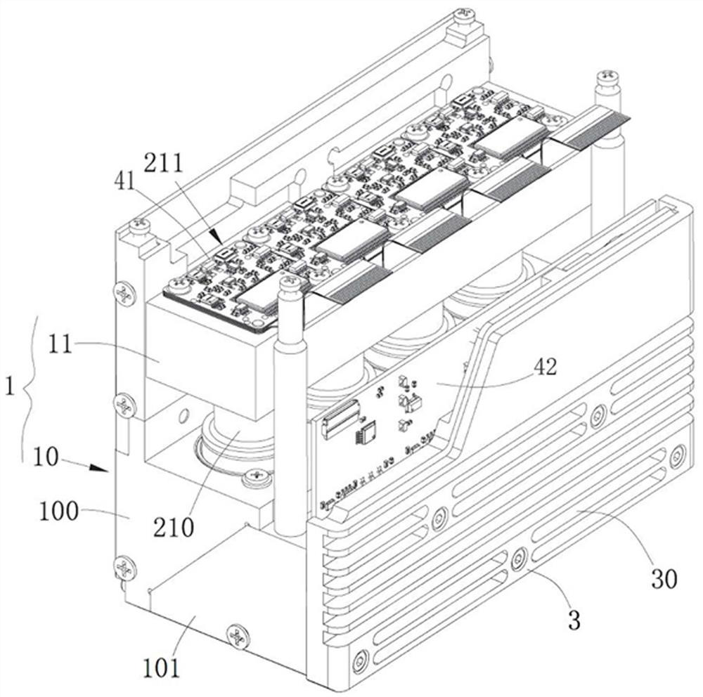
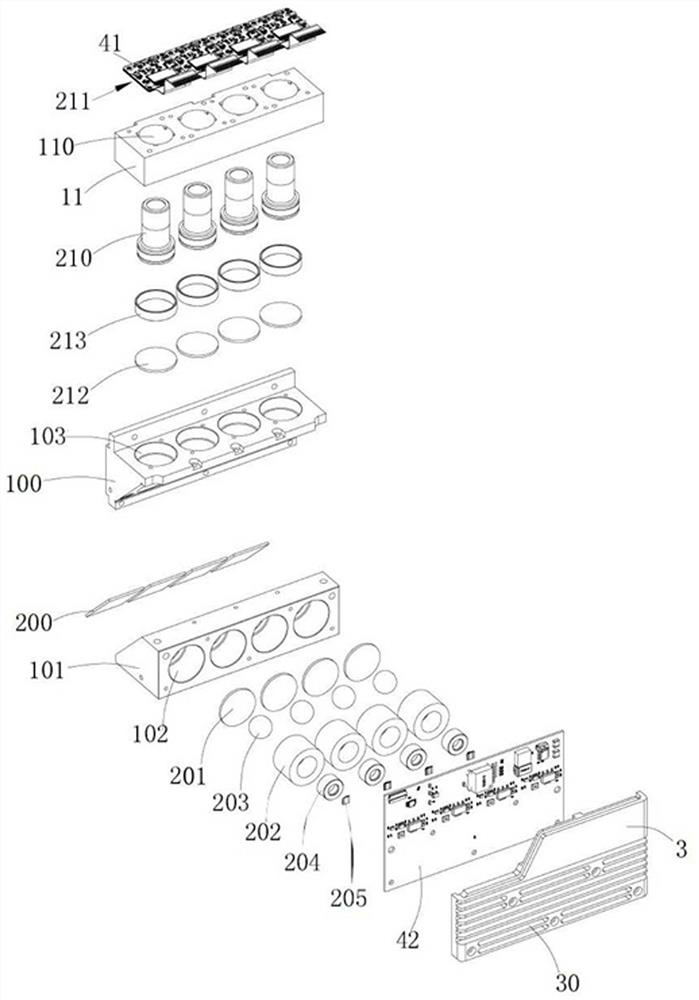
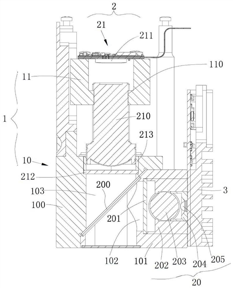
[0045] Specifically, for example, if there are three kinds of fluorescent groups added, namely red, yellow and blue, then select the above 4# fluorescence detection module, 3# fluorescence detection module, and 1# fluorescence detection module. Or, according to the specific filter band requirements, plug in and replace the appropriate first filter 201 / second filter 212, or even separate the upper body 100 from the lower body 101 to replace the dichroic with a suitable bandpass range Mirror 200.


PUM


Abstract

The invention discloses a multi-channel fluorescence PCR (polymerase chain reaction) detection system and a multi-channel fluorescence detection method, which are suitable for detecting a PCR reaction system added with various fluorophores, and the detection system comprises more than two fluorescence detection modules, each fluorescence detection module comprises a light source, a lens, a first optical filter, a dichroscope, a light emitting window, a second optical filter and an imaging module, and the fluorescence detection modules are configured to move to the positions, opposite to the PCR reaction system, of the respective light emitting windows one by one under the driving of external force so as to obtain a complete image of the PCR reaction system of a channel corresponding to the fluorophore; different fluorescence detection modules are adaptive to different types of fluorophores; and first optical filters/second optical filters/dichroscopes in different fluorescence detection modules correspond to different first wave band ranges/second wave band ranges/band pass ranges. According to the invention, a plurality of fluorescence detection modules are arranged, and signals of fluorescence channels of all reaction chambers of a PCR reaction system are sequentially acquired one by one.

Description

technical field [0001] The invention relates to the field of fluorescence detection, in particular to a multi-channel fluorescence PCR detection system and a multi-channel fluorescence detection method. Background technique [0002] During the fluorescent quantitative polymerase chain reaction (QPCR) process on the microfluidic chip, the chip usually contains multiple (several to thousands) PCR reaction chambers, and each reaction chamber contains a variety of fluorescent dye. If one light source is used to excite all fluorescent channels, the spectral utilization efficiency of the light source will be low, that is, most of the light energy will be used as background interference and affect signal acquisition. Therefore, multi-channel PCR detection technology has become a research direction. [0003] In the prior art, for example, the Chinese patent application with the publication number CN 108181239A proposes an optical system for a multi-channel fluorescence quantitativ...

Claims


Application Information

Patent Timeline
IPC IPC(8): C12M1/34C12M1/00C12Q1/686
CPCB01L7/52C12Q1/686C12Q2563/107
Inventor 马俊杰周朋郭琦
Owner 翊新诊断技术(苏州)有限公司
Why Eureka
Try Eureka