Supercharge Your Innovation With Domain-Expert AI Agents!

On-line monitoring method for internal field temperature in milling process

A milling and milling technology, applied in the field of mechanical cutting, can solve the problem of inability to use the online monitoring of the temperature of the inner field of the tool, and achieve the effects of easy implementation, low computational complexity, and good practicability

Pending Publication Date: 2022-06-21
CHONGQING UNIV
View PDF0 Cites 0 Cited by
  • Summary
  • Abstract
  • Description
  • Claims
  • Application Information

AI Technical Summary

Problems solved by technology

However, existing heat transfer inverse models consider the increase in cutting temperature as the result of the continuous action of heat flux in a single chip contact zone, while the increase in milling temperature is in the chip contact zone on multiple milling cutter edges. Therefore, the existing inverse heat transfer model cannot be applied to the on-line monitoring of the internal field temperature of the cutting tool in the milling process

Method used


Image

  • On-line monitoring method for internal field temperature in milling process
  • On-line monitoring method for internal field temperature in milling process
  • On-line monitoring method for internal field temperature in milling process

Examples


Embodiment Construction

[0069] The present invention is further described below with reference to the accompanying drawings and specific embodiments, so that those skilled in the art can better understand the present invention and implement it, but the embodiments are not intended to limit the present invention.

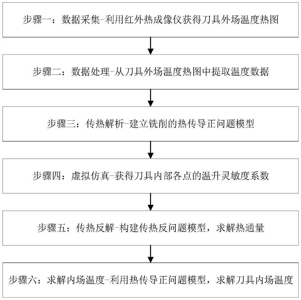
[0070] like figure 2 As shown, it is a flow chart of the on-line monitoring method of the infield temperature during the milling process of the present invention. The method for online monitoring of the internal field temperature in the milling process of the present embodiment includes the following steps:

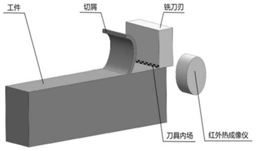
[0071] Step 1: Data acquisition: During the milling process, use an infrared thermal imager to take pictures of the tool and workpiece in real time to obtain a heat map of the tool's external field temperature for extracting the external field temperature.

[0072] The invention uses the infrared thermal imager to obtain the temperature of the external field of the tool, and uses the...


PUM


Abstract

The invention discloses an internal field temperature on-line monitoring method in a milling process, which comprises the following steps of: 1, data acquisition: shooting a cutter and a workpiece in real time by utilizing an infrared thermal imager to obtain a cutter external field temperature heat map; 2, data processing: extracting the temperature of a tool external field surface point; step 3, heat transfer analysis: establishing a heat conduction positive problem model of milling; the heat transfer process of the milling cutter in the milling process is simulated, heat fluxes of different sizes are applied to an internal field of the cutter, an internal temperature field of the cutter is solved, and temperature rise sensitivity coefficients of all points in the cutter at different temperatures are obtained; 5, heat transfer inverse solution: constructing a heat transfer inverse problem model, regarding a heat transfer inverse solution problem as an optimization problem, and solving the heat flux of the cutter internal field at each moment; and 6, solving the internal field temperature: substituting the temperature rise sensitivity coefficient of each point in the cutter and the heat flux of the internal field into the heat conduction positive problem model, and solving the internal field temperature of the cutter.

Description

technical field [0001] The invention belongs to the technical field of mechanical cutting processing, and particularly relates to an on-line monitoring method for internal field temperature during milling processing. Background technique [0002] During the machining process, a large amount of heat generated by friction and plastic deformation forms three heat sources, namely the first deformation zone (shear slip zone), the second deformation zone (chip contact zone) and the third deformation zone ( Squeeze the friction rebound zone). like figure 1 As shown, the temperature rise of the tool is mainly due to the heat generated in the chip contact area entering the tool through the contact heat conduction between the tool and the chip. Much of the heat entering the tool is concentrated in the tiny chip interface area, resulting in extremely high temperatures in this area. Existing research shows that the heat generated in the chip contact area is the main cause of tool wea...

Claims


Application Information

Patent Timeline
IPC IPC(8): G01J5/48G01K17/00B23Q17/00G06F30/23G06T7/00G06F119/08
CPCG01J5/48G01K17/00G06F30/23G06T7/0004B23Q17/00G01J2005/0077G06F2119/08G06T2207/10048
Inventor 何彦李科吴鹏程李育峰王时龙
Owner CHONGQING UNIV
Features
  • R&D
  • Intellectual Property
  • Life Sciences
  • Materials
  • Tech Scout
  • Unparalleled Data Quality
  • Higher Quality Content
  • 60% Fewer Hallucinations
Learn More