Glass connection method and device based on frit

A connection method and glass frit technology, applied in the field of glass connection process, can solve the problems of complex heating method, narrow welding window, inability to remove, etc., and achieve the effect of good connection effect, reduction of pores, and avoidance of scrap.

Pending Publication Date: 2022-06-24
HUNAN UNIV
View PDF7 Cites 0 Cited by
  • Summary
  • Abstract
  • Description
  • Claims
  • Application Information

AI Technical Summary

Problems solved by technology

To reduce the porosity and cracks in the connection process, more complicated heating methods are required, and it takes longer
Moreover, there are more or less large particles of glass frit, impurities and residual gases in the glass frit, which cannot be fully removed in the traditional sintering method, such as Figure 16 As shown in (a), a small amount of impurity type pores will be induced
At the same time, the glass frit coating obtained by the traditional sintering method needs to strictly control the input of laser energy during the welding process, otherwise it is very easy to appear such as Figure 16 The dense porosity shown in (b) results in a narrow welding window

Method used


Image

  • Glass connection method and device based on frit
  • Glass connection method and device based on frit
  • Glass connection method and device based on frit

Examples


Embodiment 1

[0059] The laser sintering method in this embodiment includes the following steps:

[0060] Step 1: ultrasonically clean the glass substrate with a mixture of distilled water and detergent.

[0061]Step 2: The glass paste is coated on the glass substrate by screen printing. Among them, the two screen plates used are screen printing plates with a film thickness of 10 μm. Screen printing pattern width 0.8mm. The final coating thickness is 4-5 μm, that is, a low-thickness glass frit coating is obtained.

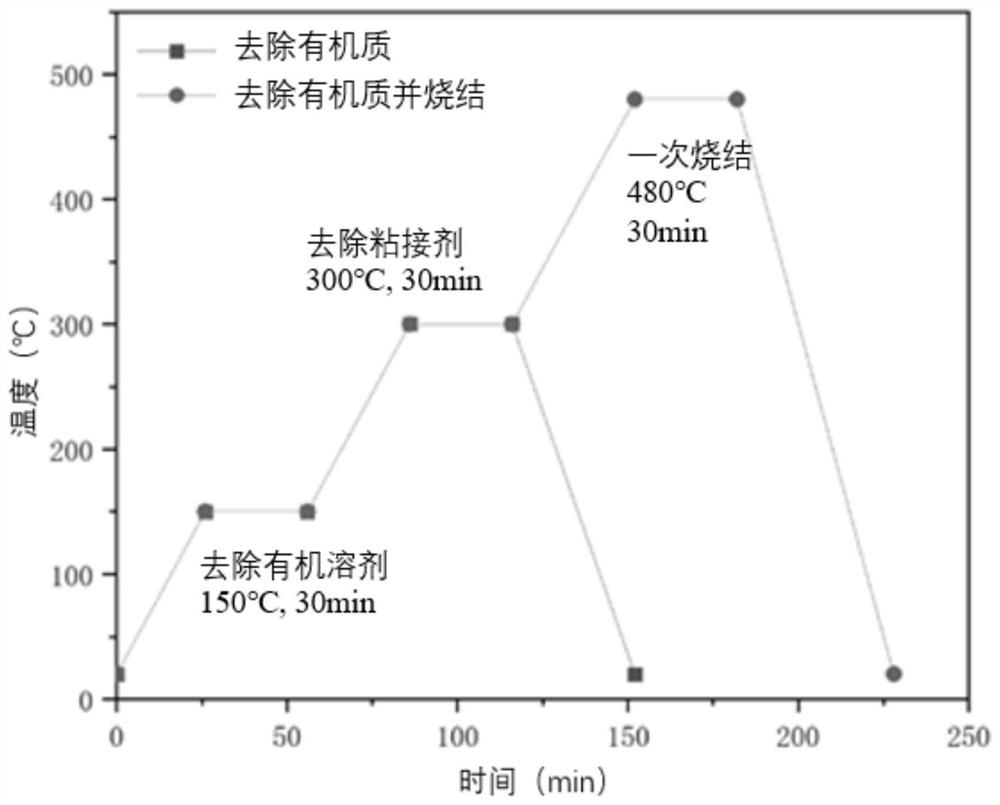
[0062] Step 3: The low-thickness glass frit coating is divided into two stages in the heating stage of the heating furnace. The heating furnace directly heats the coated glass substrate to 150 ° C in the air, keeps the temperature for 30 minutes, and removes the organic solvent; 300 ℃, heat preservation for 30min, remove the adhesive. The heating furnace heating curve is as figure 1 shown.

[0063] Step 4: Pull out the first pressing block 6, shrink the first cylinder 8, ...

Embodiment 2

[0065] The laser sintering method in this embodiment includes the following steps:

[0066] Step 1: ultrasonically clean the glass substrate with a mixture of distilled water and detergent.

[0067] Step 2: The glass paste is coated on the glass substrate by screen printing. Among them, the two screen plates used are screen printing plates with a film thickness of 25 μm. Screen printing pattern width 0.8mm. The final coating thickness is 8-10 μm, that is, a high-thickness glass frit coating is obtained.

[0068] Step 3: The high-thickness frit coating is divided into three stages during the heating stage in the furnace: organic solvent removal, binder removal and pre-sintering. heating curve such as figure 1 As shown in the figure, after removing the organic solvent and the binder, it was heated to 480 °C for 30 min, and then sintered.

[0069] Step 4: Pull out the first pressure plate 6, shrink the first cylinder 8, the second cylinder 11, the third cylinder 15, and the...


PUM

PropertyMeasurementUnit
thicknessaaaaaaaaaa
thicknessaaaaaaaaaa
thicknessaaaaaaaaaa

Abstract

The invention relates to a glass connection method and device based on frit, and the connection method is realized according to the following steps: step 1, coating frit on a glass substrate to obtain a frit coating; 2, the glass substrate coated with the frit coating is heated in a heating furnace, organic impurities in the frit coating are removed, and a heated glass substrate test piece is obtained; 3, covering the test piece in the step 2 with a glass cover plate, mounting the test piece in a special device placed on a workbench, lifting the glass cover plate, and carrying out laser sintering on the frit coating in the step 2; and step 4, pressing down a glass cover plate on the glass substrate test piece which is subjected to laser sintering in the step 3 and is provided with the frit coating, and connecting the glass substrate and the glass cover plate. Laser is used for carrying out sufficient sintering treatment on the frit coating, hidden defects in the coating are exposed, device scrapping caused in the laser welding process is avoided, formation of air holes in the follow-up laser welding process is effectively restrained, the process range of laser welding is widened, the quality requirement for the frit coating is lowered, and the production efficiency is improved. And the processing time is saved.

Description

technical field [0001] The present invention relates to a glass joining process, in particular, to a glass frit-based glass joining method and device. Background technique [0002] The glass connection process is widely used in optoelectronic device packaging, vacuum glass connection and so on. Glass frit is usually composed of glass powder, solvent, binder and filler. [0003] There are two main applications in the welding of transparent materials such as glass and glass: one is to directly weld two pieces of glass using an ultra-short pulse laser; the other is to coat the lower glass plate with a layer of opaque laser wavelengths. material, or add a layer of glass frit that is opaque to the laser wavelength in the middle, so as to increase the absorption of laser energy between the two glasses at the interface, and then transfer the absorbed energy to the upper and lower layers of glass through thermal conduction. So as to realize the welding of glass to glass. At prese...

Claims


Application Information

Patent Timeline
Patent Type & Authority Applications(China)
IPC IPC(8): C03C27/06
CPCC03C27/06
Inventor 陈根余钟沛新程少祥
Owner HUNAN UNIV
Why Eureka
Try Eureka