Tempered vacuum glass and manufacturing method thereof

A vacuum glass and tempered glass technology, applied in glass manufacturing equipment, glass tempering, manufacturing tools, etc., can solve the problems of the support point not reaching the sintering temperature, the high sintering temperature of the support point, affecting the vacuum degree, etc., and shorten the heating time. effect of time, reduced sealing temperature, reduced risk of collision

Inactive Publication Date: 2020-08-07
李长征
View PDF11 Cites 3 Cited by
  • Summary
  • Abstract
  • Description
  • Claims
  • Application Information

AI Technical Summary

Problems solved by technology

The support point is sintered together with the glass and will not move, but the sintering temperature of this kind of support point is relatively high. Due to the short heating time in the tempering furnace, the temperature in the furnace is slightly uneven, and some support points will not reach the sintering temperature.
[0005] In addition, the vacuum glass with the exhaust pipe often protrudes from the glass surface. Even if it is protected by a protective cap, the vacuum glass is prone to collision during installation, transportation and use, resulting in air leakage failure. Technology into the interior of vacuum glass
For example, the current technology uses two steps to embed the glass tube inside the glass. When the suction tube is sealed with this structure, since the heat of the infrared lamp and laser will not be completely focused on the end surface of the glass tube, the heat loss is relatively large. , It takes a longer time to seal, it is easy to cause the glass tube to degas too much and affect the vacuum degree, thereby affecting the yield, and the protective sheet of the exhaust tube is pasted on the outer surface of the glass, which will still protrude from the glass surface, causing certain safety hazards

Method used


Image

  • Tempered vacuum glass and manufacturing method thereof
  • Tempered vacuum glass and manufacturing method thereof
  • Tempered vacuum glass and manufacturing method thereof

Examples


Embodiment Construction

[0037] The present invention will be further described below in conjunction with specific embodiments.

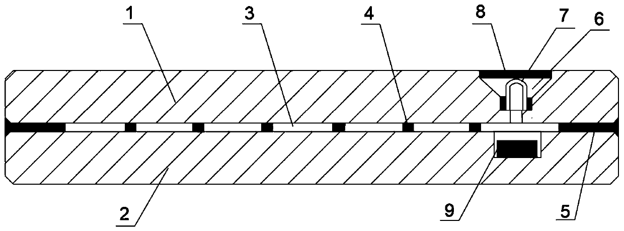
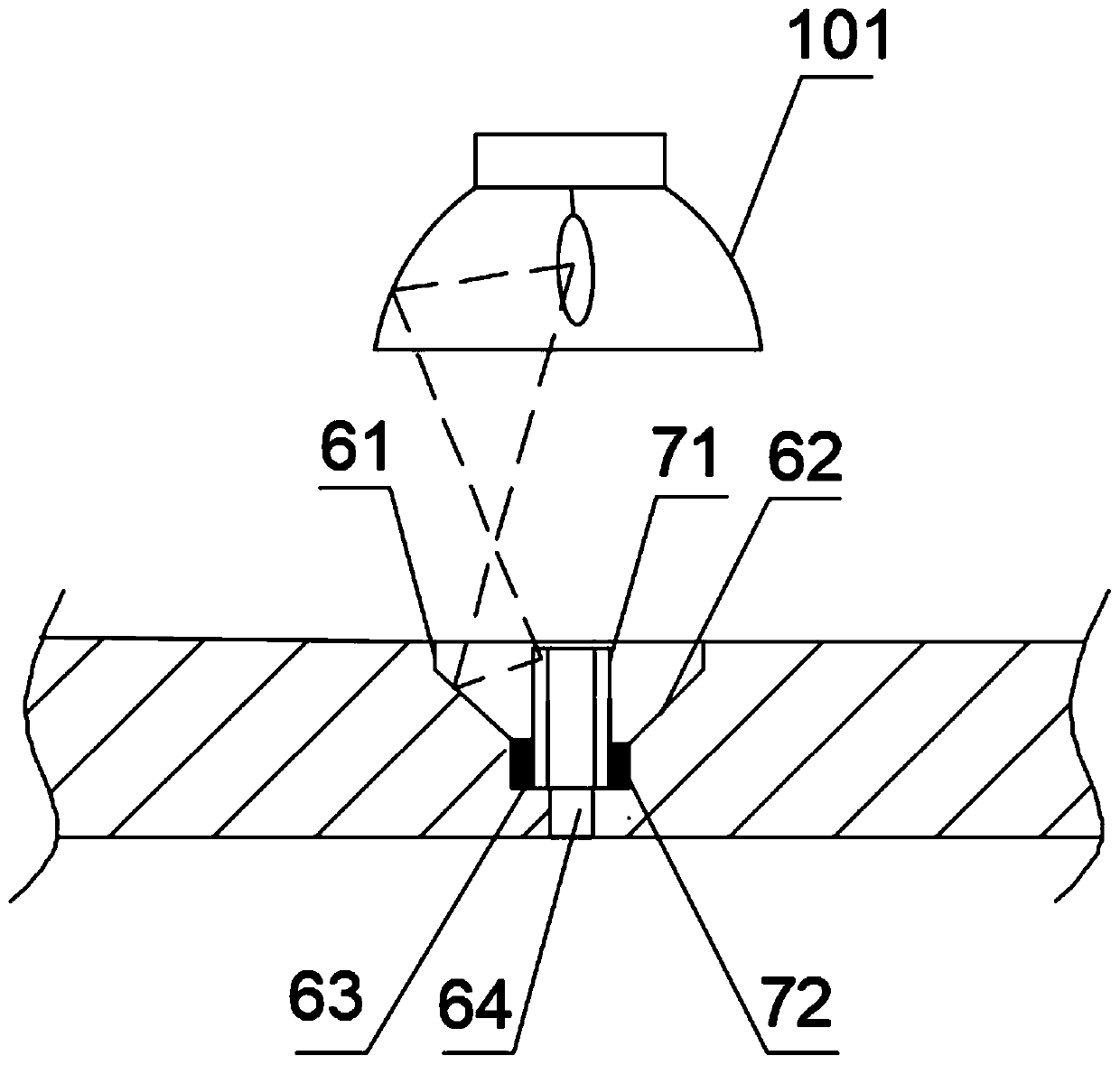
[0038] The present invention proposes a tempered vacuum glass, which comprises two tempered glass substrates 1-2, and a vacuum area 3 between the two glass substrates. The lower glass 2 is provided with ceramic glaze supports 4 at a certain interval, and the upper A piece of glass 1 is located on the support 4, and a low-temperature solder 5 is provided in the gap between the two pieces of glass, and the low-temperature solder 5 is heated by rapid heating and cooling technology to seal the surroundings of the two pieces of glass. The air extraction pipe 7 and the air extraction part 6 of the reflection surface 63 are provided with a getter 9 at a position where the bottom glass 2 faces the air extraction part 6 .

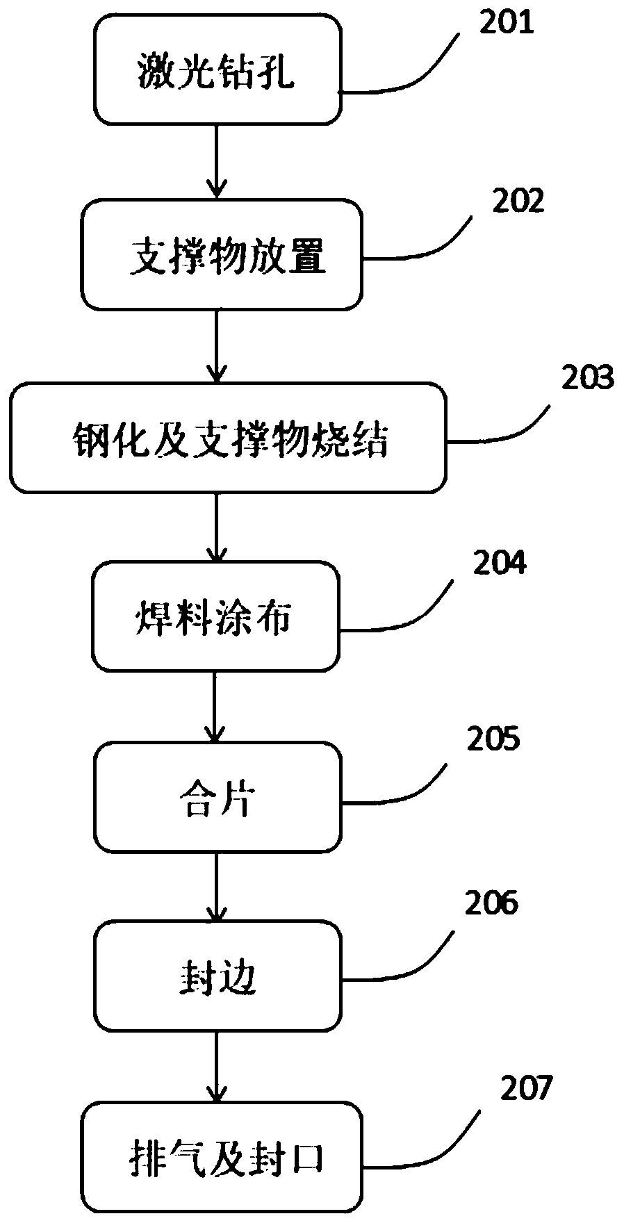
[0039] The present invention proposes a kind of preparation method of toughened vacuum glass, comprises the following steps:

[0040](1) Laser drilling 201: Fir...


PUM

PropertyMeasurementUnit
sealing temperatureaaaaaaaaaa
surface stressaaaaaaaaaa

Abstract

The invention discloses tempered vacuum glass and a manufacturing method thereof. The tempered vacuum glass comprises upper tempered glass, lower tempered glass and a vacuum area therebetween, whereina ceramic glaze supporting object is arranged between the two pieces of glass; low-temperature welding flux used for edge sealing is arranged in gaps of the four edges, and air exhaust parts with airexhaust pipes and reflecting surfaces are arranged at the corners of the upper piece of glass. The method for manufacturing the toughened vacuum glass comprises the following steps: S1, laser drilling; S2, support arrangement; S3, toughening and support sintering; S4, solder coating; S5, glass lamination; S6, edge sealing; and S7 exhaustion and sealing. In the invention, the ceramic glaze supporthas the advantages that the ceramic glaze support and the glass are sintered together; the glass is not prone to falling off, the reflection face of the glass is beneficial to concentration of sealing heat, the air suction pipe is arranged in the glass after sealing, use is safer, low-temperature welding flux and the rapid heating and cooling technology are adopted for edge sealing in the step S6, and the glass surface stress attenuation is smaller than or equal to 5%, so that the glass surface flatness is good, and the production efficiency is high.

Description

technical field [0001] The invention relates to the technical field of vacuum glass, in particular to a tempered vacuum glass and a manufacturing method thereof. Background technique [0002] Vacuum glass is a vacuum layer formed between two glass substrates. Since the conduction and convection of heat energy cannot be carried out in a vacuum, vacuum glass can more effectively insulate the transfer of heat energy and has good thermal insulation performance. Therefore, whether it is summer Or in winter, vacuum glass can make the indoor temperature not easily affected by the outdoor temperature. As buildings in various countries are developing towards zero-carbon buildings, vacuum glass has become the preferred energy-saving building material. [0003] Due to the mandatory requirements for the safety of glass in the industrial market such as building doors and windows, safe tempered vacuum glass has been gradually developed in recent years. The surface stress of tempered vacuu...

Claims


Application Information

Patent Timeline
Patent Type & Authority Applications(China)
IPC IPC(8): C03C27/10B23K26/402B23K26/382C03B27/00
CPCC03C27/10B23K26/382B23K26/402C03B27/00
Inventor 李长征
Owner 李长征
Why Eureka
Try Eureka