Steam generation system of steam turbine shaft seal system of high-temperature gas cooled reactor

A high-temperature gas-cooled reactor and generation system technology, applied in steam generation, steam generation methods, steam generation methods using heat carriers, etc., can solve problems such as low heat transfer coefficient, low steam parameters, and large power consumption. Achieve the effects of simple system equipment, high economic benefits, and large heat storage

Pending Publication Date: 2022-06-28
XIAN THERMAL POWER RES INST CO LTD
View PDF13 Cites 0 Cited by
  • Summary
  • Abstract
  • Description
  • Claims
  • Application Information

AI Technical Summary

Problems solved by technology

In this state, there are the following problems: First, the electric boiler starts slowly, the steam generation speed is slow, and it takes 18 minutes at the fastest to produce qualified steam, which does not meet the steam supply requirements of the shaft seal when the turbine falls. For the remaining steam, the external shaft seal steam supply time is required to be no more than 10 minutes; secondly, the steam parameters are low, the temperature is 220°C, the pressure is 2.0MPa, the steam parameters are almost constant and cannot be adjusted, and the nearly saturated steam cannot reach the shaft seal steam temperature above 320°C ;Thirdly, there is a high requirement for the stability of the operation of the electric boiler; finally, the electric boiler is always in a hot standby state, and the power consumption is relatively large
Patent Novel Single-tank High-temperature Energy Storage Steam Generator 202021738615.1 The heat exchange tube of the high-temperature energy storage steam generator mentioned in the outer wall of the energy storage tank can prevent corrosion of the heat exchange tube, but the processing and assembly process is difficult. The heat uniformity is not high, the heat transfer coefficient is not high, and the difference between the water temperature at the inlet of the heat exchange tube and the temperature of the tube is generally not more than 50°C, which limits the steam temperature at the outlet of the evaporator
Patent No. 202023218118.1, a shaft seal steam supply system with energy storage function, mainly mentions the energy storage supply shaft seal system, but does not mention the structure and system of the energy storage evaporator

Method used


Image

  • Steam generation system of steam turbine shaft seal system of high-temperature gas cooled reactor

Examples


Embodiment Construction

[0019] In order to make those skilled in the art better understand the solutions of the present invention, the technical solutions in the embodiments of the present invention will be clearly and completely described below with reference to the accompanying drawings in the embodiments of the present invention. Obviously, the described embodiments are only The embodiments are part of the present invention, not all of the embodiments, and are not intended to limit the scope of the present disclosure. Furthermore, in the following description, descriptions of well-known structures and techniques are omitted to avoid unnecessarily obscuring the concepts disclosed in the present invention. Based on the embodiments of the present invention, all other embodiments obtained by persons of ordinary skill in the art without creative efforts shall fall within the protection scope of the present invention.

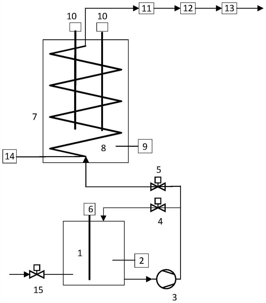
[0020] The accompanying drawings show a schematic structural diagram of an embodimen...


PUM


Abstract

The invention discloses a steam generation system of a high-temperature gas cooled reactor steam turbine shaft seal system. The steam generation system comprises a water supplementing pipeline, a constant-temperature water tank, a water tank recirculation valve, a spiral heat exchanger, a steam electric heater, a temperature reducing water device, a steam output pipeline and a fused salt storage tank. A bottom outlet of the constant-temperature water tank is divided into two paths, one path is communicated with a circulating water inlet of the constant-temperature water tank through a water tank recirculation valve, the other path is communicated with an inlet of the spiral heat exchanger through a water supply valve, and an outlet of the spiral heat exchanger is communicated with a steam output pipeline through a steam electric heater and a desuperheating water device. The spiral heat exchanger is positioned in the fused salt storage tank; a fused salt storage tank electric heater is arranged in the fused salt storage tank, and a water tank electric heater is arranged in the constant-temperature water tank; the controller is connected with the fused salt storage tank electric heater, the water tank electric heater, the steam electric heater, the attemperation water device, the water tank recirculation valve and the water supply valve, and the system can quickly generate high-parameter steam and is low in energy consumption.

Description

technical field [0001] The invention belongs to the fields of high-temperature gas-cooled reactors and new energy energy storage, and relates to a steam generation system of a high-temperature gas-cooled reactor steam turbine shaft seal system. Background technique [0002] Auxiliary steam in nuclear power plants generally comes from electric boilers. In addition to heating feed water, the auxiliary steam is also used to supply steam to the shaft seal to prevent the large shaft from being locked due to the loss of the steam to remove the shaft seal when the turbine is idling in an emergency shutdown. Therefore, when a single unit is running, the electric boiler is always in a hot standby state. In this state, there are the following problems: First, the electric boiler starts slowly, the speed of steam generation is slow, and it takes 18 minutes to produce qualified steam at the fastest, which does not meet the steam supply requirements of the shaft seal when the turbine fal...

Claims


Application Information

Patent Timeline
Patent Type & Authority Applications(China)
IPC IPC(8): F22B1/28F22B1/02F22D1/00F22G5/00F22G5/12F01D11/04
CPCF22B1/28F22B1/028F22D1/00F22G5/00F22G5/123F01D11/04
Inventor 张瑞祥余俨马晓珑高美刘锋胡杨王宇航孙文钊
Owner XIAN THERMAL POWER RES INST CO LTD
Why Eureka
Try Eureka