
Machining grinding tool positioning and adjusting device

A positioning adjustment and machining technology, applied in grinding/polishing safety devices, manufacturing tools, metal processing equipment, etc., can solve the problems of inability to guarantee the effect of grinding position, shorten the service life of equipment, and long grinding time, so as to avoid accidents The effect of breaking and adjusting the work is simple and convenient, and the yield is improved

Active Publication Date: 2022-07-05
莒南县欧亚磨料磨具有限公司
View PDF17 Cites 0 Cited by
  • Summary
  • Abstract
  • Description
  • Claims
  • Application Information

AI Technical Summary

Problems solved by technology

[0004] In the grinding work of existing grinding machines, the direction and angle of grinding are generally determined according to the experience of the grinding master, and the final grinding effect is determined according to the technology of the grinding master. Low, the yield rate is low, and the effect of the grinding position cannot be guaranteed to be the same; in addition, when the grinder is not in use, when it is accidentally hit or dropped, the grinding wheel or the joint of the grinding wheel will be broken and damaged, which will shorten the equipment. service life

Method used


Image

  • Machining grinding tool positioning and adjusting device
  • Machining grinding tool positioning and adjusting device
  • Machining grinding tool positioning and adjusting device

Examples


Embodiment 1

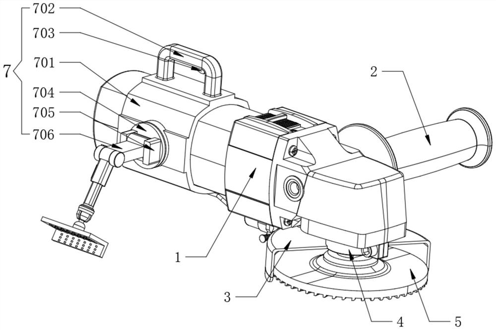
[0041] Refer to the attached Figure 5 and Image 6 , the positioning adjustment assembly 7 also includes an assembly shell 701 and a right-angle plate 713. The assembly shell 701 is sleeved on the outer surface of the grinding machine 1, the side surface of the assembly shell 701 is rotatably installed with a turntable 704, and both sides of the outer wall of the turntable 704 are fixedly provided with rotary The first seat 705, the inner sides of the two turning bases 705 are rotatably connected with the main turning rod 706, the two turning bases 707 are fixedly arranged on both sides of the end of the main turning rod 706, and the inner sides of the two turning bases 707 are rotatably connected with auxiliary turning Rod 708, the side wall of the auxiliary rotation rod 708 is fixedly provided with a side card slot 712, the inner part of the auxiliary rotation rod 708 is movably inserted with an insert rod 709, and the end of the auxiliary rotation rod 708 is fixedly provid...

Embodiment 2

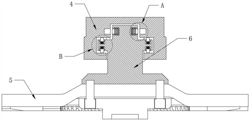
[0045] Refer to the attached Figure 2-4 The top end of the working shaft 4 is equidistantly fixed with locking holes 41 , and the bottom end of the working shaft 4 is equidistantly fixed with offset grooves 42 .

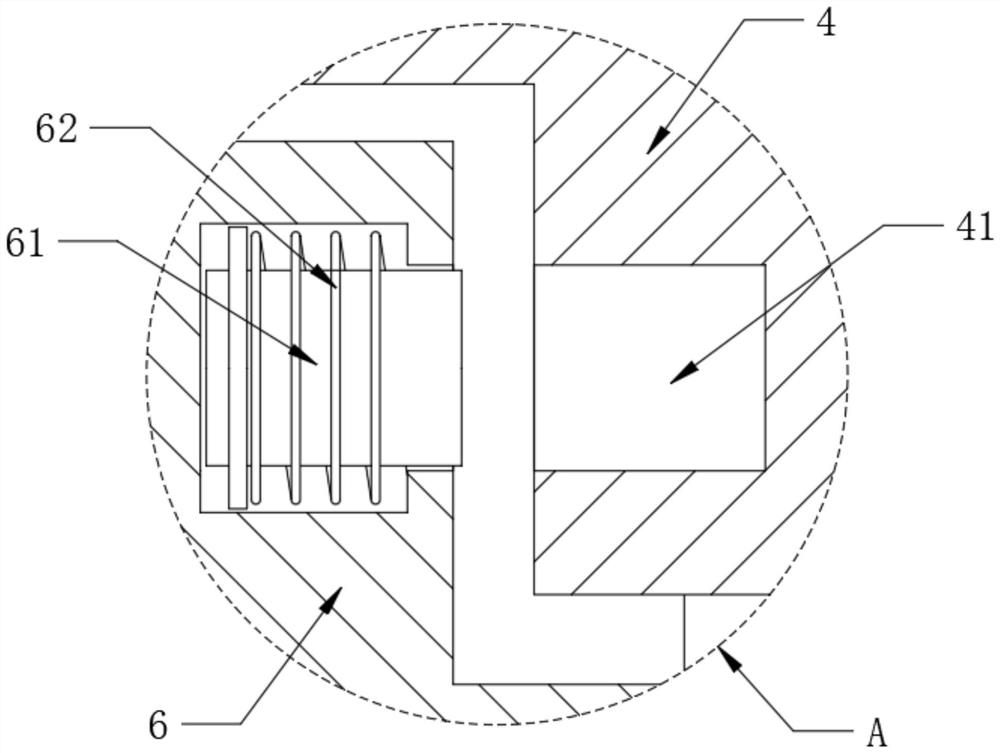
[0046] Refer to the attached image 3 , the inside of the top edge of the inscribed shaft 6 is movably installed with a locking block 61, the outer surface of the locking block 61 is sleeved with a spring 62, and the end of the locking block 61 is movably inserted into the inside of the locking hole 41, The cross-sectional area of ​​the locking block 61 is the same as the cross-sectional area of ​​the locking hole 41. During the high-speed rotation of the grinding wheel 5 driven by the working shaft 4, each locking block 61 will move away from the center of rotation under the action of centrifugal force. , and is inserted into the corresponding locking hole 41 , and no offset will occur between the working shaft 4 and the inscribed shaft 6 .

[0047] Refer to the ...

Embodiment 3

[0050] Refer to the attached Figure 9 , the transmission assembly 8 also includes a built-in rod 801, the built-in rod 801 is movably inserted inside one side of the wheel cover 3, the bottom of the built-in rod 801 is fixedly provided with a baffle-804, the upper surface of the baffle-804 and the lower surface of the wheel-cover 3 are between They are connected by a spring three 805, and the spring three 805 is sleeved on the outer surface of the built-in rod 801. The bottom end of the built-in rod 801 is rotated and provided with a fitting wheel 802, and the outer wall of one end of the fitting wheel 802 is fixedly connected with a connecting rod. 803 , a displacement slot 31 is fixedly opened on one side of the wheel housing 3 , and the connecting rod 803 is movable through the displacement slot 31 .

[0051] Refer to the attached Figure 10 , a support 806 is fixed on one side of the lower surface of the grinding machine 1, and a tension rod 807 is movably interspersed a...


PUM


Abstract

The invention belongs to the technical field of machining, and particularly relates to a machining grinding tool positioning adjusting device which comprises a grinding machine, a first handle is fixedly arranged on the side wall of one end of the grinding machine, a working shaft is rotationally arranged at one end of the grinding machine, and an inner connecting shaft is connected to the bottom end of the working shaft. A grinding wheel is fixedly installed at the bottom end of the inner connecting shaft through a screw, a positioning adjusting assembly is movably installed at the end, away from the working shaft, of the grinding machine, a wheel cover is fixedly arranged on the lower surface of one end of the grinding machine, a transmission assembly is fixedly arranged on one side of the wheel cover, and a dust suction device is fixedly arranged on the lower surface of the grinding machine. The grinding position of the grinding wheel can be fixed, grinding work can be rapidly completed conveniently, safety of the connecting position of the grinding wheel can be guaranteed, the grinding wheel is prevented from being accidentally broken after being impacted, dust near a motor at the tail end of the grinding machine can be absorbed, and the dust is prevented from entering equipment.

Description

technical field [0001] The invention belongs to the technical field of machining, and in particular relates to a positioning and adjusting device for an abrasive tool for machining. Background technique [0002] The full name of the electric grinding machine is the reciprocating electric polishing and grinding machine (also known as the file grinding machine). It is widely used in the finishing and surface polishing of the mold industry. It is a substitute for similar pneumatic products. Powerful grinding performance up to 150% of the load; using a complete set of safety concepts: touch start, automatic stop, wear-free electronic braking system EBS, quick clamping system QUICKin, power-off restart lock and soft start; strong The self-supporting motor construction, the switch module is dust-proof and durable. [0003] Problems existing in the prior art: [0004] In the grinding work of the existing grinding machines, the direction and angle of grinding are generally determi...

Claims


Application Information

Patent Timeline
Patent Type & Authority Applications(China)
IPC IPC(8): B24B23/02B24B41/00B24B55/00B24B55/10
CPCB24B23/02B24B41/007B24B55/00B24B55/102Y02P70/10
Inventor 金海龙
Owner 莒南县欧亚磨料磨具有限公司
Learn More