
Gas lift and pump lift combined lifting well drilling device without marine riser and parameter design method of well drilling device

A riser and drilling technology, applied to drilling equipment and methods, driving devices for drilling in boreholes, drilling equipment, etc., can solve the problems of increasing drilling costs and risks, reduce power, improve reliability, and improve parameters Optimized effect

Active Publication Date: 2022-07-08
CHINA UNIV OF PETROLEUM (EAST CHINA)
View PDF10 Cites 0 Cited by
  • Summary
  • Abstract
  • Description
  • Claims
  • Application Information

AI Technical Summary

Problems solved by technology

If this technology is applied in deep sea, the lifting capacity of the injection pump will be very high, which will undoubtedly increase the cost and risk of drilling

Method used


Image

  • Gas lift and pump lift combined lifting well drilling device without marine riser and parameter design method of well drilling device
  • Gas lift and pump lift combined lifting well drilling device without marine riser and parameter design method of well drilling device
  • Gas lift and pump lift combined lifting well drilling device without marine riser and parameter design method of well drilling device

Examples


Embodiment 1

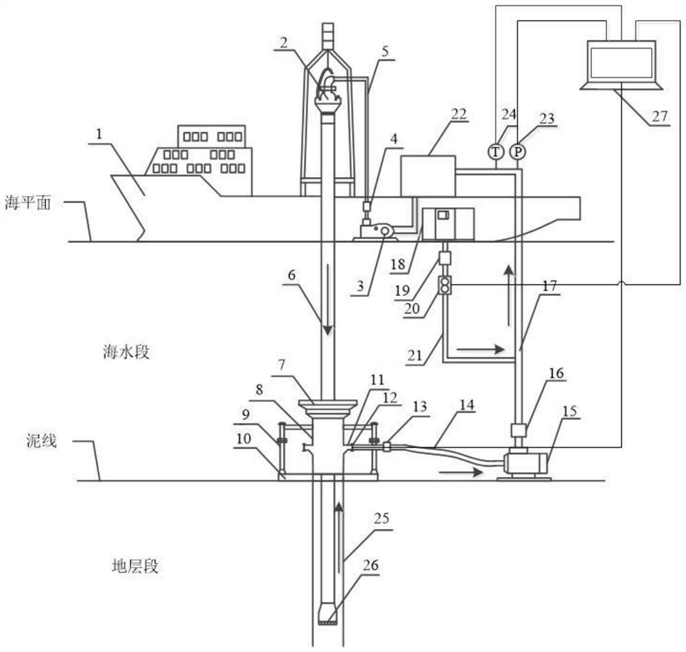
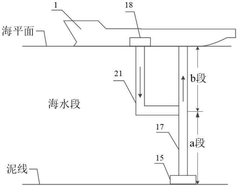
[0110] A drilling device with riserless gas lift and pump lift combined lift, such as Figure 1-2 As shown, it includes a drilling vessel 1, a drilling fluid injection system, a subsea drilling fluid suction system, a drilling fluid lifting system, a surface drilling fluid processing device 22, a data monitoring system and a data processing system;

[0111] The drilling fluid injection system is installed on the drilling ship 1. During drilling, the drilling fluid is pumped into the drill pipe 6 through the drilling fluid injection system to form a flow circulation in the wellbore to achieve the purpose of breaking the rock; the wellbore includes the drill pipe 6 and the casing 25, which are surrounded by The air is the annular part between the wellbore and the drill pipe. The subsea drilling fluid suction system is used to divert the cuttings and drilling fluid returned from the annular space to realize the sealing between the wellbore and the seawater; the drilling fluid is l...

Embodiment 2

[0115] A drilling device without riser gas lift, pump lift combined lift, as described in Embodiment 1, the difference is that the drilling fluid injection system includes a mud pump 3, a first flow control valve 4, a drilling fluid connected in sequence After injection into pipeline 5 and top drive 2, the drilling fluid stored in the mud tank is sucked by the mud pump 3, and then injected into the pipeline 5 along the drilling fluid under the action of the pump, and then sent into the drill pipe 6 through the top drive 2. The rod 6 flows to the drill bit 26 to achieve the purpose of assisting rock breaking.

[0116] The subsea drilling fluid suction system is installed on the subsea wellhead, and its functions are mainly to straighten down the drilling tool, provide an interface for the drilling fluid return line 14, and isolate the top of the annulus and the surrounding environment. The subsea drilling fluid suction system includes a subsea mud suction device 7, an external ...

Embodiment 3

[0118] A drilling device without riser gas lift, pump lift combined lift, as described in Embodiment 2, the difference is that the pump lift system includes a subsea lift pump 15, a third flow control valve 16 and a drilling fluid upward return Pipeline 17, the subsea lifting pump 15 is installed on the seabed, and is used to provide power for the upturning cuttings and drilling fluid. The inlet of the subsea lifting pump 15 is connected with the drilling fluid return line 14 of the subsea drilling fluid suction system, and the outlet is connected to the drilling fluid return line 14. The drilling fluid return line 17 of the three flow control valve 16 is connected, and the end of the drilling fluid return line 17 is connected to the sea surface drilling fluid processing device 22;

[0119] The gas lift system includes an air compressor 18, a fourth flow control valve 19, a gas flow meter 20 and a gas injection line 21. The air compressor 18 is installed on the drilling ship 1,...


PUM


Abstract

The invention relates to a marine riser-free gas lift and pump lift combined lifting drilling device and a parameter design method thereof, and belongs to the field of ocean deepwater oil and gas drilling engineering, the device comprises a drilling ship, a drilling fluid injection system, a seabed drilling fluid suction system, a drilling fluid lifting system, a sea surface drilling fluid processing device, a data monitoring system and a data processing system; a gas lift process is creatively introduced, and a gas lift and pump lift combined lifting scheme is adopted, so that the power of the submarine pump can be greatly reduced, the construction cost is saved, and the reliability of a lifting system is improved; according to parameter design, the influence of gas, liquid, solid and other multi-phase and multi-component in a deepwater gas lift passage on the flowing state and the rock carrying effect of upward-returning drilling fluid is considered, a multi-phase flowing model in a drilling fluid upward-returning pipeline and a parameter optimization model of gas lift and pump lift combined lifting are established, and the wellbore pressure and the rock debris concentration under different working conditions can be accurately calculated; and effective guidance is provided for efficient drilling and production of deepwater oil gas.

Description

technical field [0001] The invention relates to a drilling device without riser gas lift, pump lift combined lift and a parameter design method thereof, belonging to the technical field of marine deep water oil and gas drilling engineering. Background technique [0002] The rapid development of the economy has made mankind's dependence on oil and gas resources increase year by year. According to experts' estimates, 40% of the world's total oil and gas reserves in the future will come from the deep sea, and the future alternative energy "combustible ice" will also mainly come from the deep sea. In order to maintain the steady growth of oil and gas, it is necessary to Rely on the safe and efficient development of offshore oil and gas. Compared with onshore and shallow sea drilling, deep-sea drilling environment is more complex and faces greater difficulties and challenges. Problems with rig openings such as late formation of weak seabed; increased wave and current loads and p...

Claims


Application Information

Patent Timeline
Patent Type & Authority Applications(China)
IPC IPC(8): E21B7/12E21B7/124E21B4/14E21B21/08E21B43/12E21B47/00E21B47/06E21B47/07
CPCE21B7/12E21B7/124E21B4/14E21B21/08E21B43/122E21B47/00E21B47/06E21B47/07E21B43/123
Inventor 王志远刘徽孙宝江王金堂王雪瑞陈刚孙大林
Owner CHINA UNIV OF PETROLEUM (EAST CHINA)
Learn More