Multi-stage hydraulic drive hydrogen compressor control system and method

A control system and control method technology, applied in the container discharge method, multi-stage pump, pump control, etc., can solve the problems of hydrogen overheating, equipment utilization maximization, etc., to increase the filling speed, reduce the aging speed, The effect of improving operating efficiency

Pending Publication Date: 2022-07-12
江苏氢枫能源装备有限公司 +1
View PDF5 Cites 0 Cited by
  • Summary
  • Abstract
  • Description
  • Claims
  • Application Information

AI Technical Summary

Problems solved by technology

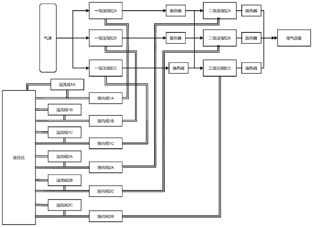
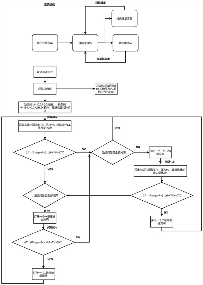
[0004] The purpose of the present invention is to overcome the technical problems that the existing hydrogen compressors in the background technology cannot maximize the utilization rate of equipment and hydrogen filling is prone to overheating, so as to provide a multi-stage hydraulically driven hydrogen compressor control system and method

Method used


Image

  • Multi-stage hydraulic drive hydrogen compressor control system and method
  • Multi-stage hydraulic drive hydrogen compressor control system and method

Examples


Embodiment Construction

[0035] The technical solutions of the present invention will be clearly and completely described below with reference to the accompanying drawings. Obviously, the described embodiments are a part of the embodiments of the present invention, but not all of the embodiments. Based on the embodiments of the present invention, all other embodiments obtained by those of ordinary skill in the art without creative efforts shall fall within the protection scope of the present invention.

[0036] In the description of the present invention, it should be noted that the terms "installed", "connected" and "connected" should be understood in a broad sense unless otherwise expressly specified and limited. Dismantling connection, or integral connection; it can be a mechanical connection or an electrical connection; it can be directly connected or indirectly connected through an intermediate medium, or it can be the internal connection of two components, which can be wireless connection or Wir...


PUM


Abstract

The invention discloses a multistage hydraulically-driven hydrogen compressor control system and method.The multistage hydraulically-driven hydrogen compressor control system comprises compression oil cylinders which comprise a plurality of first-stage compression oil cylinders and a plurality of second-stage compression oil cylinders, and each first-stage compression oil cylinder and each second-stage compression oil cylinder are arranged in series through a gas pipeline; the air supply source independently supplies power to the first-stage compression oil cylinder and the second-stage compression oil cylinder; the plurality of first heat exchangers are respectively connected in series between the first-stage compression oil cylinder and the second-stage compression oil cylinder; a first-stage reversing valve and a first-stage compression overflow valve are further connected in series between each first-stage compression oil cylinder and the corresponding access port of the hydraulic station, and a second-stage reversing valve and a second-stage compression overflow valve are further connected in series between each second-stage compression oil cylinder and the corresponding access port of the hydraulic station; and the gas utilization equipment is connected to the tail end of the second-stage compression oil cylinder. The displacement of the compressor is dynamically adjusted according to actual working condition requirements so as to adapt to various different working conditions, the operation efficiency of the hydraulic drive compressor is improved, and stable operation of hydrogenation facilities is guaranteed.

Description

technical field [0001] The invention relates to the technical field of hydrogen compressors, in particular to a multi-stage hydraulically driven hydrogen compressor control system and method. Background technique [0002] In the existing hydrogen refueling station applications, the gas compressors are mostly conventional hydraulic drives, and are generally single-stage compression or single-cylinder two-stage compression. Under the condition of constant external conditions, the compressor displacement is fixed, and the compression During the working process of the machine, the displacement of the compressor is passively changed according to the intake pressure of the compressor. Since hydrogen long-tube trailers are generally used as the source to supply gas to the station in the hydrogen refueling station, the intake pressure is a dynamic change. When filling the vehicle, the hydrogen flow into the fuel cell vehicle needs to be adjusted to prevent over-temperature during th...

Claims


Application Information

Patent Timeline
Patent Type & Authority Applications(China)
IPC IPC(8): F15B11/16F17C5/06F17C7/00F04B25/00F04B49/00F04B35/02F04B37/12
CPCF15B11/161F17C5/06F17C7/00F04B25/00F04B49/002F04B35/00F04B37/12F17C2250/0631F17C2260/023Y02E60/32
Inventor 方沛军宣锋崔亮亮伍远安曹俊
Owner 江苏氢枫能源装备有限公司
Why Eureka
Try Eureka