Vacuum generator and construction method and application thereof

A technology of vacuum generators and construction methods, which is applied in infrastructure engineering, machines/engines, waterway systems, etc., and can solve problems such as piping, leaking from pressurized water layers, difficulty in achieving expected results, and complicated equipment assembly to achieve accelerated Large precipitation capacity, automatic well-washing infiltration path, low cost effect

Pending Publication Date: 2022-07-15
JIANGSU HYDRAULIC ENG CONSTR
View PDF4 Cites 0 Cited by
  • Summary
  • Abstract
  • Description
  • Claims
  • Application Information

AI Technical Summary

Problems solved by technology

In addition, although there are a small number of vacuum tube wells on the market, the existing vacuum tube well technology generally uses a vacuum pump to pump out the air in the tube well, which often has small negative pressure, small influence range, high failure rate, complicated equipment assembly, and high operating costs. High disadvantage
[0004] When the permeability coefficient of the soil layer is small and the precipitation depth of the foundation pit is large, it is difficult for any of the above precipitation methods to achieve the expected effect, and it is difficult to deal with and solve the piping and water leakage in the confined water layer that are often encountered in the construction of deep foundation pits. And other issues

Method used


Image

  • Vacuum generator and construction method and application thereof

Examples


Embodiment 1

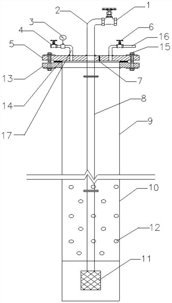
[0035] like figure 1 As shown, this embodiment provides a vacuum generator, which includes a tube well, a submersible electric pump 11 , an outlet pump pipe 8 , a drain pipe 2 , a water inlet pipe 16 and an exhaust pipe 17 .

[0036] The tube well is made of steel pipe with a diameter of 273mm and a wall thickness of 6mm. One end of the tube well is welded and closed with a 6mm steel plate, and the other end is open and sealed with a flange cover plate 5 . The tube well includes a connected tube well solid tube part 9 and a tube well flower tube part 10 , and the tube well flower tube part 10 is provided with a number of water inlet holes 12 . The length of the tube well flower tube part 10 is determined according to the depth and soil layer required for precipitation. The outside of the tube well flower tube part 10 is provided with a filter screen.

[0037] The submersible electric pump 11 is arranged at the closed end of the tube well. The submersible electric pump 11 is c...

Embodiment 2

[0040] This embodiment provides a construction method of the vacuum generator described in Embodiment 1, comprising the steps of:

[0041] (1) Leveling the site and removing underground obstacles;

[0042] (2) Measuring and releasing well location;

[0043] (3) The drilling rig is in place;

[0044] (4) Start drilling;

[0045] (5) Hole-forming inspection, since the precipitation capacity of the vacuum generator is stronger than that of ordinary tube wells, the recommended hole-forming diameter is 800mm;

[0046] (6) The tube well is placed, and the height of the tube well exposed to the ground is 0.5~1m;

[0047](7) Backfill filter material, in order to ensure the water output of the well and prevent the influx of fine sand into the well, take 3.5~4.5m from the top of the tube well as the dividing point, and the diameter between the tube well and the borehole wall below the dividing point is 1.5 m. ~3mm gravel and coarse sand backfill, the backfill should be uniform, and ...

Embodiment 3

[0054] This embodiment provides an application of the vacuum generator described in Embodiments 1 and 2 in hydraulic engineering, comprising the following steps:

[0055] (1) Close the exhaust valve 4 on the exhaust pipe 17 and the water inlet valve 6 on the water inlet pipe 16, turn on the submersible electric pump 11, and the water in the pipe wells (9, 10) is discharged along the water outlet pipe 8 and the drain pipe 2 At the same time, negative pressure is formed in the closed space in the tube well, and the groundwater enters the tube well under the action of negative pressure and is continuously discharged;

[0056] (2) Observe the negative pressure in the tube well through the positive and negative pressure gauge 3. When air enters the tube well to reduce the negative pressure, turn off the submersible electric pump 11, open the exhaust valve 4 and the water inlet valve 6, and pass the water inlet pipe 16. Inject water into the tube well until the exhaust pipe 17 overf...


PUM


Abstract

The invention discloses a vacuum generator and a construction method and application thereof, and belongs to the technical field of hydraulic engineering. The vacuum generator comprises a tube well, a submersible electric pump, a water outlet pump tube, a water drainage tube, a water inlet tube and an exhaust tube; one end of the tube well is closed, the other end of the tube well is opened and sealed by a flange cover plate, and a plurality of water inlet holes are formed in a tube body, close to the closed end, of the tube well; the submersible electric pump is arranged at the closed end of the tube well, the submersible electric pump is connected with one end of the water outlet pump pipe, and the other end of the water outlet pump pipe is connected with the drainage pipe; a water inlet pipe and an exhaust pipe are arranged on the flange cover plate, and a positive and negative pressure gauge is arranged on the exhaust pipe. The vacuum generator provided by the invention is simple in structure and convenient to operate, and can realize underground soil layer precipitation, automatic well washing, smooth underground water permeation path and solve the piping problem.

Description

technical field [0001] The invention belongs to the technical field of hydraulic engineering, and particularly relates to a vacuum generator and a construction method and application thereof. Background technique [0002] During foundation pit excavation of hydraulic engineering or other earthwork construction, groundwater and surface water will continuously infiltrate into the pit. If it is not removed in time, it will not only deteriorate the construction conditions, but also cause slope instability, quicksand of the foundation pit, and uplift of the pit bottom. Piping will also affect the bearing capacity of the foundation, and even cause safety accidents such as slope collapse, causing delays in the construction period, increasing costs, and causing damage to the surrounding environment to a certain extent. It is very important to keep the working surface dry and the soil stable. [0003] Construction dewatering and drainage can be divided into two categories: open ditc...

Claims


Application Information

Patent Timeline
Patent Type & Authority Applications(China)
IPC IPC(8): E02D19/10E03F5/22F04D13/08
CPCE02D19/10E03F5/22F04D13/08
Inventor 舒兆亚吴山柏张伟李文亮李均虎陈博李逸川闵瑞张昌盛曹志国王申王庆亚吴明明吴世新常胜
Owner JIANGSU HYDRAULIC ENG CONSTR
Why Eureka
Try Eureka