110kV transformer low-voltage side outgoing cable contact cabinet

A technology of transformer low-voltage side and contact cabinet, which is applied in the direction of transformer/inductor coil/winding/connection, cable joint, cable installation, etc. It can solve the problems of high heating temperature at the connection end, hidden accidents, and large path resistance. To achieve the effect of increasing the contact area, avoiding oil leakage and reducing resistance

Pending Publication Date: 2022-07-15
南水北调东线山东干线有限责任公司
View PDF0 Cites 0 Cited by
  • Summary
  • Abstract
  • Description
  • Claims
  • Application Information

AI Technical Summary

Problems solved by technology

[0003] In order to facilitate the unattended management of the substation of the pumping station, the high-voltage power transformation and distribution method mostly adopts COMPASS-145 air-insulated high-voltage combined electrical appliances. There are three oil-filled bushings at the outlet end of the low-voltage side of the transformer. Since each oil-filled bushing is respectively connected to three high-voltage cable terminal joints to the incoming cabinet of the high-voltage room, each high-voltage cable has a relatively thick diameter, so it is connected to the terminal Finally, the push-pull force on the oil-filled bushing is very large, resulting in leakage of the oil-filled bushing of the transformer, which poses a great safety hazard, and the path resistance is large, resulting in high heating temperature at the connection end, and the internal temperature change of the transformer cannot be obtained in time and discover potential accidents

Method used


Image

  • 110kV transformer low-voltage side outgoing cable contact cabinet
  • 110kV transformer low-voltage side outgoing cable contact cabinet
  • 110kV transformer low-voltage side outgoing cable contact cabinet

Examples


Embodiment Construction

[0024] In order to clearly illustrate the technical features of the solution, the present invention will be described in detail below through specific embodiments and in conjunction with the accompanying drawings.

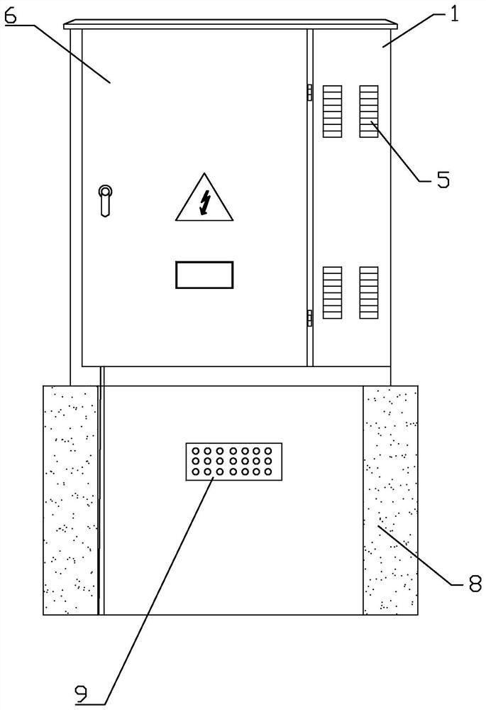
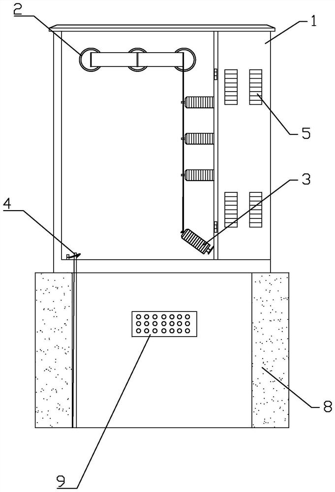
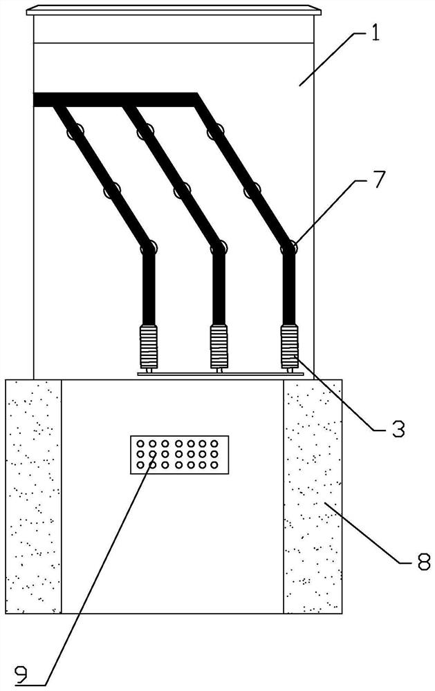
[0025] like Figure 1-8 As shown in the figure, a 110kV transformer low-voltage side outgoing cable connection cabinet, including cabinet 1, is provided with three round holes at equal intervals on the north side of the cabinet, and each round hole is installed with a high-voltage wall bushing 2 through stainless steel bolts , the external terminal of the high-voltage wall bushing 2 is connected with the transformer low-voltage tank oil-filled bushing through the three-phase copper busbar, and the three high-voltage wall bushings are sequentially installed with yellow, green and red high-voltage heat pipes. Shrinkable sleeve; an openable cabinet door 6 is installed on the south side of the cabinet 1 to separate the cabinet 1 into a left cabinet and a right cabinet,...


PUM


Abstract

A 110kV transformer low-voltage side outlet cable contact cabinet comprises a cabinet body, three round holes are formed in the north side of the cabinet body at equal intervals, each round hole is provided with a high-voltage wall bushing through a stainless steel bolt, and the external wiring end of each high-voltage wall bushing is connected with a transformer low-voltage groove oil filling bushing through a three-phase copper busbar. Yellow, green and red high-voltage heat-shrinkable bushings are sequentially mounted on the three high-voltage wall bushings; an openable cabinet door is installed on the south side of the cabinet body so as to divide the cabinet body into a left box body and a right box body, a three-phase copper busbar and an internal wiring end of a high-voltage wall bushing are arranged in the left box body, and a valve-shaped lightning arrester is connected to the lower end of the three-phase copper busbar so as to instantly lead external high voltage generated by external thunder and lightning into a substation grounding electrode at the bottom of the cabinet body; multiple rows of waterproof heat dissipation holes are formed in the west side of the cabinet body, and a stainless steel filter screen is installed in the cabinet body; an openable cabinet door is installed on the east side of the cabinet body, and a plurality of European style touchable cable joints are arranged in the cabinet body.

Description

Technical field: [0001] The invention relates to a 110kV transformer low-voltage side outgoing cable connection cabinet. Background technique: [0002] The transformer is a device that uses the principle of electromagnetic induction to change the AC voltage. The main components are the primary coil, the secondary coil and the iron core. The main functions are: voltage transformation, current transformation, impedance transformation, isolation, voltage regulation, etc.; For: distribution transformers, power transformers, fully sealed transformers, combined transformers, dry-type transformers, oil-immersed transformers, single-phase transformers, electric furnace transformers, rectifier transformers, reactors, anti-interference transformers, lightning protection transformers, box-type transformers Electrical test transformers, corner transformers, high current transformers, excitation transformers, etc. [0003] In order to facilitate the unattended management of the substati...

Claims


Application Information

Patent Timeline
IPC IPC(8): H02B1/20H02B1/16H02B1/30H02B1/50H02B1/46H02G13/00H02G15/10H02G15/16H02G3/08H02G3/16G01K13/00H01F27/29
CPCH02B1/202H02B1/207H02B1/16H02B1/30H02B1/303H02B1/50H02B1/46H02G13/40H02G15/10H02G15/16H02G3/08H02G3/081H02G3/088H02G3/16G01K13/00H01F27/29Y02A30/14
Inventor 韩业庆李典基张兆军于跃瞿潇黄九常任庆旺陆发兵张向辉孙路
Owner 南水北调东线山东干线有限责任公司
Why Eureka
Try Eureka