Layered stripping and recycling device for photovoltaic module
A recycling device and photovoltaic module technology, which is applied in the field of photovoltaic module layered peeling and recycling devices, can solve problems such as incomplete classification, high energy consumption for crushing and recycling, and cumbersome procedures, and achieve high peeling efficiency
- Summary
- Abstract
- Description
- Claims
- Application Information
AI Technical Summary
Problems solved by technology
Method used
Image
Examples
Embodiment 1
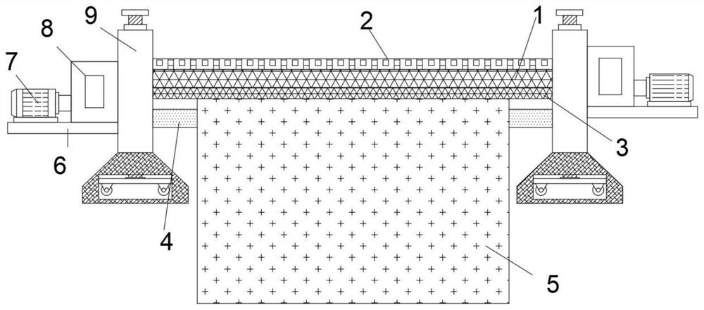
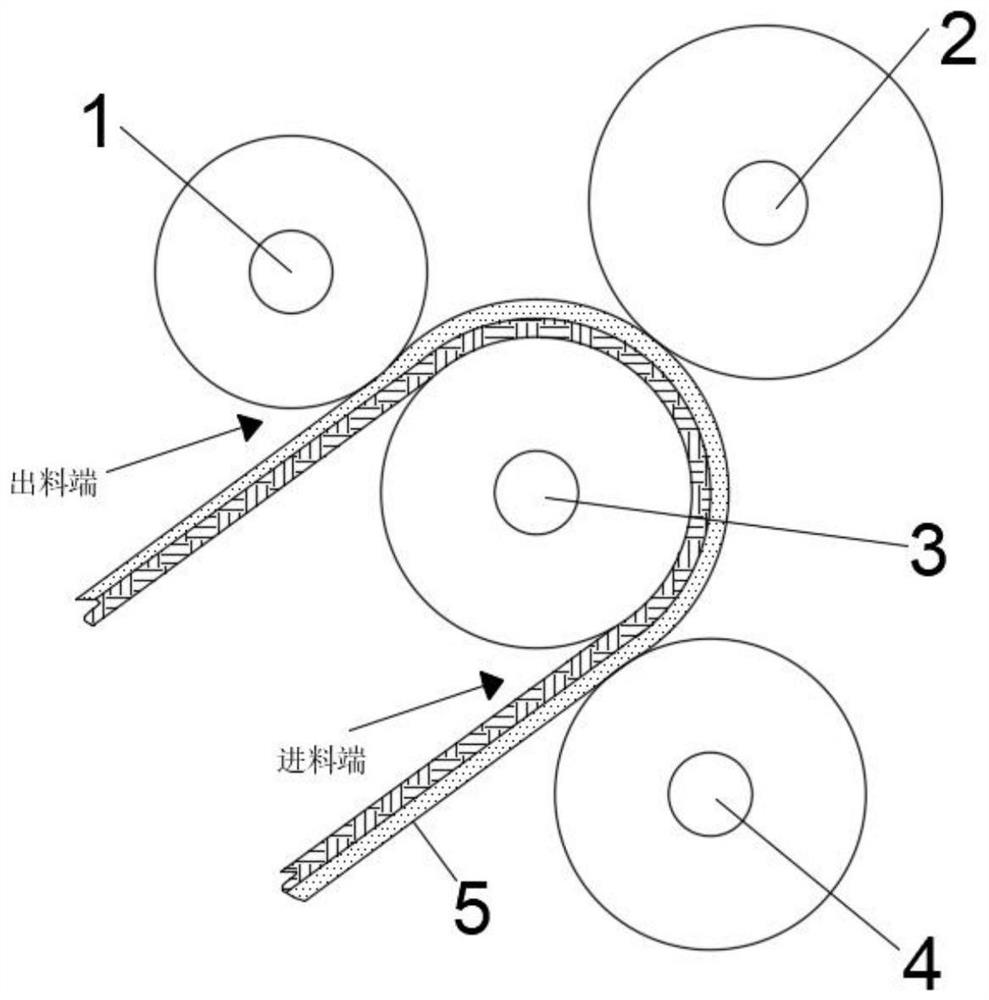
[0027] refer to Figure 1-3 , a layered peeling recovery device for photovoltaic modules, including two racks 9, and a No. 1 roller 1, No. 2 roller 2, No. 3 roller 3 and No. Between the roller 3 and the fourth roller 4 is the feed end for stripping the scrapped frameless frameless junction box assembly 5, and between the first roller 1 and the third roller 3 is the scrapped frameless frameless junction box assembly 5. At the discharge end of the peeling, the third roller 3 and the second roller 2 are connected with power components.
Embodiment 2
[0029] Improvement on the basis of the first embodiment: the photovoltaic module delamination recovery device in this embodiment includes two racks 9, and a No. 1 roller 1, a No. 2 roller 2, and a No. 3 roller are rotatably installed between the two racks 9. Roll 3 and No. 4 roll 4, No. 1 roll 1 and No. 3 roll 3 are steel rolls, and the outer surface is provided with a drawing pattern. The tooth block for peeling off the outer glass, between the third roller 3 and the fourth roller 4 is the feed end for peeling the scrapped frameless frameless junction box assembly 5, and between the first roller 1 and the third roller 3 is the scrap The frameless and no junction box assembly 5 is peeled off at the discharge end, the third roller 3 and the second roller 2 are connected with a power assembly, and the power assembly includes a mounting plate 6 fixedly installed on one side of the frame 9. A motor 7 and a gearbox 8 are fixedly installed on the top, the output shaft of the motor 7...
Embodiment 3
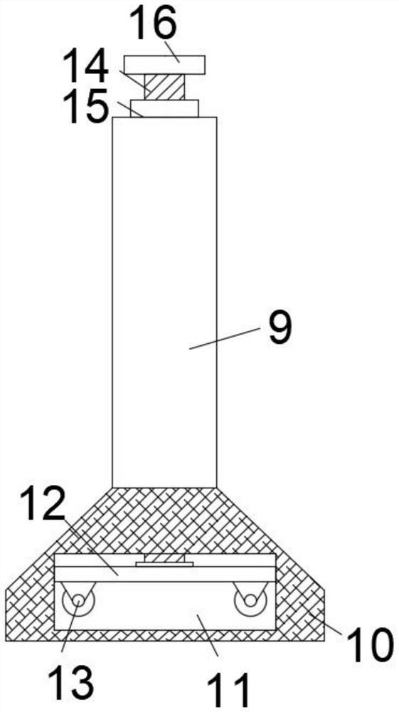
[0031] Improvement on the basis of the second embodiment: it also includes a receiving cavity 11 arranged on the outrigger 10, and a sliding plate 12 is slidably connected in the receiving cavity 11. The bottom of the sliding plate 12 is provided with four universal wheels 13, and the sliding plate 12 A screw 14 is rotatably connected to the top of the housing, and the top of the screw 14 penetrates the frame 9 and extends to the top of the frame 9, and the screw 14 and the frame 9 are threadedly connected. The bottom of the storage cavity 11 is provided with four universal wheels 13 corresponding through holes. A bearing 15 is fixedly installed on the top of the frame 9 , an adjusting handle 16 is fixedly connected to the top of the screw rod 14 , and the screw rod 14 penetrates the inner ring of the bearing 15 and is fixedly connected with the inner ring of the bearing 15 .
PUM
 Abstract
Description
Claims
Application Information
 - R&D Engineer
- R&D Manager
- IP Professional
- Industry Leading Data Capabilities
- Powerful AI technology
- Patent DNA Extraction
Browse by: Latest US Patents, China's latest patents, Technical Efficacy Thesaurus, Application Domain, Technology Topic, Popular Technical Reports.
© 2024 PatSnap. All rights reserved.Legal|Privacy policy|Modern Slavery Act Transparency Statement|Sitemap|About US| Contact US: help@patsnap.com


