Eureka AIR delivers breakthrough ideas for toughest innovation challenges, trusted by R&D personnel around the world.

Device and method for recycling hydrogen production acidic water

A technology of acidic water and carbonate, applied in chemical instruments and methods, multi-stage water/sewage treatment, water/sludge/sewage treatment, etc., to achieve the effect of reducing environmental CO2 emissions and solving the problem of acidic water discharge

Pending Publication Date: 2022-07-22
SHAANXI YANCHANG PETROLEUM GRP
View PDF0 Cites 0 Cited by
  • Summary
  • Abstract
  • Description
  • Claims
  • Application Information

AI Technical Summary

Problems solved by technology

[0003] The present invention proposes a device and method for recycling acidic water for hydrogen production, which are used to overcome the above-mentioned problems or at least partially solve or alleviate the above-mentioned problems

Method used


Image

  • Device and method for recycling hydrogen production acidic water

Examples


Embodiment 1

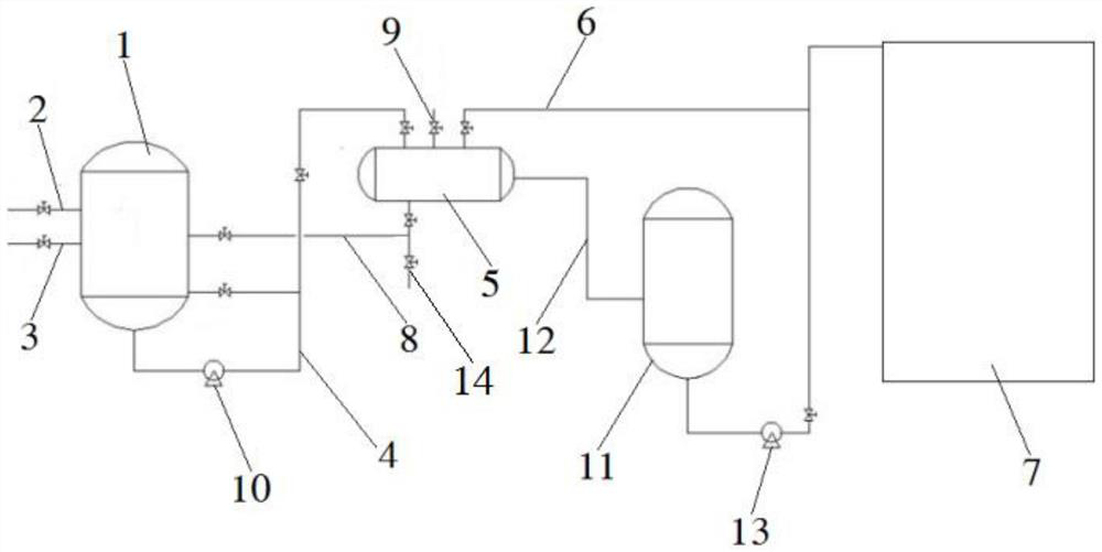
[0023] refer to figure 1 , the embodiment of the present invention provides a hydrogen production acid water recycling device, including: a mixing tank 1, a membrane separator 5 and an evaporative dryer 7; the mixing tank 1 is connected with an acid water inlet pipeline 2 and an alkali Liquid inlet pipeline 3, the mixing tank 1 is also connected with a mixed liquid outlet pipeline 4; the inlet end of the membrane separator 5 is connected with the mixed liquid outlet pipeline 4, and the membrane separator 5 is connected to the A concentration outlet pipeline 6 is also provided; the inlet of the evaporative dryer 7 is communicated with the concentration outlet pipeline 6 .

[0024] The hydrogen production unit produces a higher CO 2 The acid water is introduced into the mixing tank 1 through the acid water inlet pipeline 2, and the sodium hydroxide solution is introduced through the lye water inlet pipeline 3. The mixing tank 1 is provided with an acid-base corrosion-proof stir...

Embodiment 2

[0029] refer to figure 1 , On the basis of Embodiment 1, the membrane separator 5 is also provided with a return water pipeline 8 , and the return water pipeline 8 leads back to the mixing tank 1 .

[0030] The lower area of ​​the filter membrane in the membrane separator 5 is connected to the return water pipeline 8, and the return water pipeline 8 is connected to the mixing tank 1. If the membrane fails, the water separated by the filter membrane of the membrane separator 5 can be returned to the mixing tank. In the tank 1, it can also be discharged to other places through the return water bypass 14 on the return water pipeline 8.

Embodiment 3

[0032] refer to figure 1 , On the basis of Example 1, the membrane separator 5 is also provided with a fresh water inlet pipeline 9 .

[0033] The membrane separator 5 can also pass fresh water through the fresh water inlet pipe 9 to clean the concentration outlet pipe 6 .


PUM


Abstract

The invention provides a hydrogen production acidic water recycling device. The hydrogen production acidic water recycling device comprises a mixing tank, a membrane separator and an evaporation dryer, the mixing tank is connected with an acidic water inlet pipeline and an alkali liquor inlet pipeline, and is also connected with a mixed liquor outlet pipeline; the inlet end of the membrane separator is connected with a mixed liquid outlet pipeline, and the membrane separator is also provided with a concentrated outlet pipeline; and an inlet of the evaporation dryer is communicated with the concentration outlet pipeline. The invention also provides a hydrogen production acidic water recycling method which comprises the following steps: step S001, introducing acidic water containing carbonate and bicarbonate into the mixing tank, introducing alkali liquor containing hydroxyl into the mixing tank, and stirring and neutralizing to generate carbonate and bicarbonate solution; s002, introducing the carbonate and bicarbonate solution into a membrane separator, and carrying out membrane separation to obtain concentrated carbonate and bicarbonate solution; and S003, introducing the concentrated carbonate and bicarbonate solution into an evaporation drying device to obtain carbonate and bicarbonate crystals.

Description

technical field [0001] The invention belongs to the field of petrochemical industry, and in particular relates to a hydrogen-producing acid water recycling device and method. Background technique [0002] The hydrogen production unit owned by Yanchang Petroleum started construction in February 2013 and was handed over in October 2013. This unit is a supporting device for the diesel hydrogenation unit. Desulfurization part, steam reforming part, shift reaction and heat recovery part, steam production system part and PSA purification part, etc. The raw material refining part adopts the method of ZnO for fine desulfurization to carry out the raw material purification, and the reforming part adopts the hydrocarbon-steam reforming method. Hydrogen and product parts adopt PSA purification and purification process to produce hydrogen. The hydrogen production capacity of the hydrogen production unit is 20,000 standard / hour. The designed raw materials are catalytic dry gas, hydrogen...

Claims


Application Information

Patent Timeline
IPC IPC(8): C02F9/10
CPCC02F9/00C02F1/66C02F1/44C02F1/04
Inventor 李勇勇吴红梅井争平惠晓武郭琪姚朝刚王利锋张燕子
Owner SHAANXI YANCHANG PETROLEUM GRP
Why Eureka
Eureka Blog
Learn More