Thermal-shock-proof high-voltage-resistant optical cable

A high-voltage, optical cable technology, applied in the direction of fiber mechanical structure, etc., can solve the problems of test result interference, signal loss, loss, etc., and achieve the effect of improving survivability, improving compressive performance, and improving working life.

Active Publication Date: 2022-07-22
YANGTZE OPTICAL FIBRE & CABLE CO LTD +1
View PDF14 Cites 3 Cited by
  • Summary
  • Abstract
  • Description
  • Claims
  • Application Information

AI Technical Summary

Problems solved by technology

Optical fiber sensors, such as fiber grating-based sensors and F-P cavity-based sensors, are all affected by temperature. Under the impact effect of drastic temperature changes, the test results are disturbed, and cannot be effectively ruled out.
In special application environments, such as deep wells in oil fields, the temperature rises sharply during the working period of the drill bit, and the temperature drops sharply when the drill bit stops working. With the working law of the drill bit, the sensing optical cable is repeatedly in the sharp rise and drop of the ambient temperature. The impact of thermal shock can lead to inaccurate test results and signal loss. In severe cases, test results will fail and even fiber optics will be damaged.
On the other hand, oil wells not only have drastic temperature changes, but also the high-pressure environment is not conducive to the work of the very fragile optical fiber, which is easy to break and cause signal loss. Ordinary optical fibers are difficult to use in high-temperature and high-pressure environments. If necessary, special protection is required. Long-term and stable operation in deep wells of oil fields, which also limits the application of optical fibers in deep wells of oil fields

Method used


Image

  • Thermal-shock-proof high-voltage-resistant optical cable
  • Thermal-shock-proof high-voltage-resistant optical cable

Examples


Embodiment Construction

[0035] In order to make the objectives, technical solutions and advantages of the present invention clearer, the present invention will be further described in detail below with reference to the accompanying drawings and embodiments. It should be understood that the specific embodiments described herein are only used to explain the present invention, but not to limit the present invention. In addition, the technical features involved in the various embodiments of the present invention described below can be combined with each other as long as there is no conflict with each other.

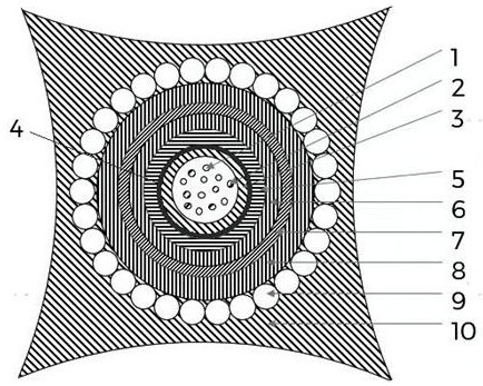
[0036] refer to figure 1 , figure 2 , a thermal shock-resistant and high-voltage optical cable, comprising optical cable subunits, PI film 4, fiber paste 5, inner steel pipe 6, foam layer 7, outer steel pipe 8 and outer sheath 10 arranged in sequence from inside to outside, The optical cable subunit includes a subunit sheath 3 and a plurality of optical fibers 1 arranged in the subunit sheath 3. ...


PUM

PropertyMeasurementUnit
thicknessaaaaaaaaaa
thicknessaaaaaaaaaa
thicknessaaaaaaaaaa

Abstract

The optical cable comprises an optical cable subunit, a PI film, fiber paste, an inner-layer steel pipe, a foaming layer, an outer-layer steel pipe and an outer sheath which are sequentially arranged from inside to outside, the optical cable subunit comprises a subunit sheath and a plurality of optical fibers, the PI film wraps the outer surface of the subunit sheath, the inner-layer steel pipe, the foaming layer and the outer-layer steel pipe, and the outer-layer steel pipe wraps the PI film. The thickness of the outer-layer steel pipe ranges from 0.9 mm to 1.0 mm, the thickness of the foaming layer ranges from 1.0 mm to 1.5 mm, and the thickness of the inner-layer steel pipe ranges from 0.25 mm to 0.3 mm. Through the inner and outer double-layer steel pipes, the compression resistance of the optical cable is ensured, the tensile property of the optical cable is also ensured, the optical cable can cope with a high-temperature and high-pressure environment, the foaming layer provides buffering, thermal insulation and other effects for the optical cable, the survival ability of the optical cable is further improved, and the service life of the optical cable is prolonged. The optical cable has the characteristics of high voltage endurance capability, strong tensile capability, corrosion resistance, high temperature resistance and the like.

Description

technical field [0001] The invention belongs to the field of optical cables, and more particularly, relates to a thermal shock-resistant and high-voltage-resistant optical cable. Background technique [0002] Oil and gas development requires monitoring of downhole temperature and pressure. Through downhole testing, the dynamic change information of oil and gas reservoirs in the process of oil production can be grasped, and the measured information can be comprehensively analyzed to obtain the distribution status of oil, gas and water in the oil reservoir, thereby understanding the development dynamics of the entire oil area. This provides a scientific basis for adjusting and optimizing oilfield development plans and improving crude oil recovery. [0003] In the early days of oilfields, mechanical downhole pressure gauges were used with low precision. They were generally only used to measure downhole static pressure, and are now rarely used. Electronic pressure gauges are n...

Claims


Application Information

Patent Timeline
Patent Type & Authority Applications(China)
IPC IPC(8): G02B6/44
CPCG02B6/4427G02B6/443G02B6/4436G02B6/4479G02B6/4488
Inventor 陈学山李国巍汪方伟周聪烨楚一帆杨向荣祁林
Owner YANGTZE OPTICAL FIBRE & CABLE CO LTD
Why Eureka
Try Eureka