Miniaturized L-to-C wave band multichannel adaptive frequency converter
A frequency converter, C-band technology, applied in the field of miniaturized L-to-C-band multi-channel adaptive frequency converter, can solve the problems of few frequency converter channels, narrow frequency range, low transmission efficiency, etc., and achieve a wide frequency range. , small size, many channels
- Summary
- Abstract
- Description
- Claims
- Application Information
AI Technical Summary
Problems solved by technology
Method used
Image
Examples
Embodiment 1
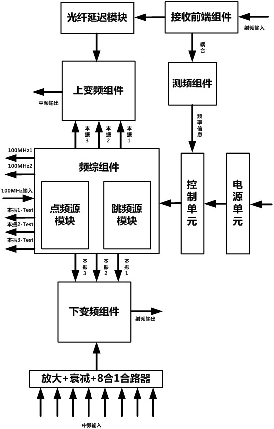
[0036] A miniaturized L-to-C-band multi-channel adaptive frequency converter of this embodiment, such as Figure 1-8 As shown, it includes an L to C band miniaturized multi-channel adaptive frequency converter, including a receiving front end, an optical fiber delay module, a frequency measurement component, a frequency synthesis component, an up-conversion component and a down-conversion component,
[0037] The output RF signal of the receiving front-end component is connected to the up-conversion component through the optical fiber delay module, and the coupled output RF signal is connected to the frequency measurement module to realize frequency measurement, and at the same time, the frequency measurement result is given, including frequency measurement information, received signal power information, and pulse width. , repeat frequency and other information, and output trigger pulse; receiving front-end components at least include multiple amplifiers, multiple attenuators an...
Embodiment 2
[0039] This embodiment is further optimized on the basis of Embodiment 1, such as figure 2 As shown in the figure, the receiving front end receives the RF signal, passes through the coarse adjustment attenuator and the low noise amplifier in turn, and then enters the coupler for coupling. After coupling, amplification, and attenuation gain adjustment, the RF signal and the coupled signal are output. The coupling output gain is 15dB~20dB , the coupling degree of the microstrip coupler is 18dB±1dB.
[0040] The other parts of this embodiment are the same as those of Embodiment 1, and thus are not repeated here.
Embodiment 3
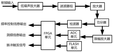
[0042] This embodiment is further optimized on the basis of the above-mentioned Embodiment 1 or 2, such as image 3As shown in the figure, the frequency measurement component amplifies and attenuates the RF signal, and then processes it by the ADC chip and the FPGA unit, and then outputs the frequency-related information after processing by the look-up table frequency measurement unit and the weighted average unit, which can realize the frequency of the coupled signal output by the receiving front-end component. Measure and output the measured frequency information to the control unit to complete the control of the frequency hopping of the local vibration. At the same time, the frequency measurement component should also give frequency measurement results, including frequency measurement information, received signal power information, pulse width, repetition frequency and other information, and output trigger pulses at the same time, adapting to signal types including pulse, li...
PUM
 Abstract
Description
Claims
Application Information
 - R&D
- Intellectual Property
- Life Sciences
- Materials
- Tech Scout
- Unparalleled Data Quality
- Higher Quality Content
- 60% Fewer Hallucinations
Browse by: Latest US Patents, China's latest patents, Technical Efficacy Thesaurus, Application Domain, Technology Topic, Popular Technical Reports.
© 2025 PatSnap. All rights reserved.Legal|Privacy policy|Modern Slavery Act Transparency Statement|Sitemap|About US| Contact US: help@patsnap.com


