Cast-in-place aqueduct supporting frame structure based on BIM technology and design process

A technology of design process and support frame, applied in design optimization/simulation, artificial waterways, water conservancy projects, etc., can solve problems such as weak adaptability of support frame, insufficient support frame stability, etc., to improve accurate modeling and modeling operation Improved effect

Pending Publication Date: 2022-07-26
THE GUANGDONG NO 3 WATER CONSERVANCY & HYDRO ELECTRIC ENG BOARD CO LTD
View PDF1 Cites 0 Cited by
  • Summary
  • Abstract
  • Description
  • Claims
  • Application Information

AI Technical Summary

Problems solved by technology

[0005] For this reason, the present invention provides a kind of cast-in-place aqueduct support frame structure and design process based on BIM technology, in order to overcome the insufficient st

Method used


Image

  • Cast-in-place aqueduct supporting frame structure based on BIM technology and design process
  • Cast-in-place aqueduct supporting frame structure based on BIM technology and design process

Examples


Example Embodiment

[0052] In order to make the purpose and advantages of the present invention clearer, the present invention will be further described below with reference to the embodiments; it should be understood that the specific embodiments described herein are only used to explain the present invention, but not to limit the present invention.

[0053] Preferred embodiments of the present invention are described below with reference to the accompanying drawings. It should be understood by those skilled in the art that these embodiments are only used to explain the technical principle of the present invention, and are not intended to limit the protection scope of the present invention.

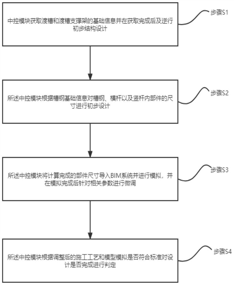
[0054] see figure 1 As shown in the figure, the design process of the cast-in-place aqueduct support frame based on BIM technology is characterized in that it includes:

[0055] Step S1, before the modeling starts, the central control module obtains the basic information of the aqueduct and the aqueduct su...


PUM


Abstract

The invention relates to the technical field of aqueduct construction, in particular to a cast-in-place aqueduct supporting frame design process based on a BIM technology, and the process comprises the steps that S1, a central control module obtains basic information of an aqueduct and an aqueduct supporting frame and carries out preliminary structural design after obtaining is completed; s2, the central control module preliminarily designs the sizes of internal parts of the channel steel, the transverse rod and the vertical rod according to the basic information of the channel steel; s3, the center control module imports the calculated component size into a BIM system and simulates the component size; and S4, the central control module judges whether the design is completed or not according to whether the adjusted construction process and model simulation meet the standard or not. A supporting frame structure of the cast-in-place aqueduct supporting frame design process based on the BIM technology comprises channel steel, transverse rods, vertical rods and an operation platform. According to the method, more accurate modeling of the cast-in-place aqueduct supporting frame is achieved, the stability of the supporting frame is improved, and the adaptability of the supporting frame to different environments and weather conditions is improved.

Description

technical field [0001] The invention relates to the technical field of aqueduct construction, in particular to a cast-in-place aqueduct support frame structure and design process based on BIM technology. Background technique [0002] Aqueduct refers to an overhead aqueduct that conveys water flow across rivers, valleys, depressions and roads. It is widely used for water transportation in life and production, and also used for flood discharge, sand discharge, etc. Large aqueducts can also be navigable. Aqueducts are widely used in many water conservancy projects and water diversion projects, creating many distinctive modern aqueducts. Diverting water for irrigation and solving residents' domestic water use has become a prominent livelihood project. Aqueducts, as one of the water conservancy facilities, began to be built on a large scale in this context. It is one of the effective ways to solve long-distance water delivery. [0003] Existing aqueducts generally use prefabr...

Claims


Application Information

Patent Timeline
IPC IPC(8): G06F30/13G06F30/20E02B5/02G06F119/02
CPCG06F30/13G06F30/20E02B5/02G06F2119/02
Inventor 卢宾邓远新冯微李翔张子惠柴波周汉臣
Owner THE GUANGDONG NO 3 WATER CONSERVANCY & HYDRO ELECTRIC ENG BOARD CO LTD
Why Eureka
Try Eureka