Airplane electric actuator energy management system based on flight control information and control method

An energy management system and energy control technology, which is applied in aircraft transmission, aircraft power transmission, aircraft power plant, etc., can solve the problems of limited energy impact suppression ability, sudden increase of power supply network voltage, and voltage drop shock of power supply network, etc. Achieve good energy management effect, fast response speed, and small system weight

Active Publication Date: 2022-07-29
BEIHANG UNIV +1
View PDF21 Cites 0 Cited by
  • Summary
  • Abstract
  • Description
  • Claims
  • Application Information

AI Technical Summary

Problems solved by technology

[0002]A new generation of multi-electric aircraft is equipped with electric actuators on multiple rudder surfaces such as elevators and ailerons for flight actuation. The power supply network absorbs energy and feeds back energy to the power supply network along the load. The energy feedback will cause a sudden increase in the voltage of the power supply network, causing a step-down impact on the power supply network at the moment of startup. At the same time, when a small disturbance occurs in the working voltage of the electric actuator, it will absorb The current causes the instability of the power supply system
Aiming at the impact of the electric actuator on the power supply network, a dissipative solution is adopted: a power resistor is added inside the motor driver of the electric actuator to consume the braking energy, but the energy utilization rate is low and the thermal load of the system is increased. Not suitable for high-speed or stealth aircraft with outstanding thermal conflicts
[0003]Energy storage scheme: add energy storage system at the load end for local energy storage, and local energy storage at the electric actuator end can suppress the target electric action However, this method has limited ability to suppress the energy impact in the entire power supply network; adding an energy storage system to the main bus bar for unified energy storage, centralized energy storage can adopt a single energy storage structure to simultaneously suppress The impact of multiple electric actuators on the power supply network, but in the existing method of adding an energy storage system to the main bus bar for unified energy storage, the generation of control signals all depends on the current voltage state of the main bus bar, and can only be generated after the impact occurs. For energy management, the system response is slower and less robust

Method used


Image

  • Airplane electric actuator energy management system based on flight control information and control method
  • Airplane electric actuator energy management system based on flight control information and control method
  • Airplane electric actuator energy management system based on flight control information and control method

Examples


Embodiment 1

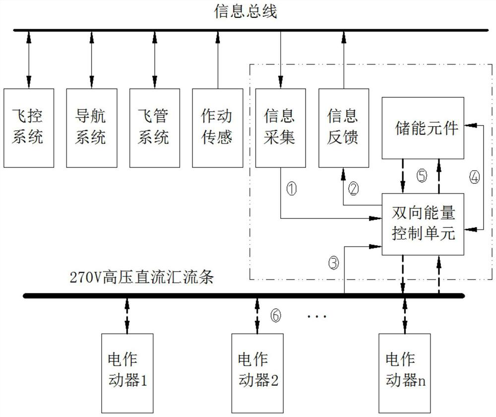
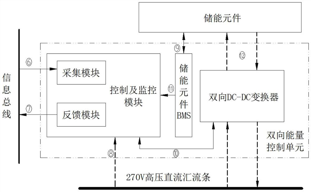
[0054] Figure 1-2 Shown is a preferred embodiment of the aircraft electric actuator energy management system based on flight control information. The aircraft electric actuator energy management system based on flight control information includes a bidirectional energy control unit and an energy storage element. an energy storage system, the energy storage system is on the main bus bar of the airborne power supply network, and the bidirectional energy control unit includes a control and monitoring module and a bidirectional DC-DC converter;

[0055] The control and monitoring module is used to collect the status information of the 270V high-voltage DC bus bar connected to the aircraft flight control, the navigation system information and the electric actuator, and predict the voltage change of the 270V high-voltage DC bus bar at the next moment based on the above collected information. The DC bus bar voltage stabilization generates control signals for the target;

[0056] Th...

Embodiment 2

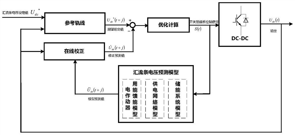
[0081] Figure 4 Shown is a preferred embodiment of an aircraft electric actuator energy management control method based on flight control information. Based on the above-described flight control information-based aircraft electric actuator energy management system in Embodiment 1, the method steps are:

[0082] S1: The acquisition module of the control and monitoring module collects the aircraft flight control and navigation system information on the avionics information bus, and calculates the energy consumption of the electric actuator at the next moment or Feed energy E i (t+Δt);

[0083] The control and monitoring module selects the best working SOC tolerance corresponding to the energy storage element in the current flight stage according to the information of the aircraft flight control and navigation system, and monitors the energy storage element through the energy storage element capacity management device BMS in cooperation with the control and monitoring module. ...


PUM


Abstract

The invention relates to an aircraft electric actuator energy management system based on flight control information and a control method, the system comprises a bidirectional energy control unit and an energy storage element, the bidirectional energy control unit comprises a control and monitoring module interacting with aircraft flight control and navigation system information, a bidirectional DC-DC converter and an energy storage element capacity management device BMS; the method comprises the steps that a bus bar voltage prediction model of the control and monitoring module is based on aircraft flight control and navigation system information and state information of a bus bar connected with an electric actuator, rolling optimization calculation and feedback correction are adopted to predict the impact effect, and bidirectional energy flow between an energy storage element and the bus bar is controlled; the system has the advantages of being simple in structure, light in weight, good in energy management effect and robustness, high in anti-jamming capability, capable of working efficiently all the time and the like, and the energy flow relation between the electric actuators in the same power supply network and the power supply network is managed in a unified mode. The impact of the energy consumption change of the electric actuator on the power supply network can be inhibited in time when the airplane is in large maneuver or the load is repeatedly switched.

Description

technical field [0001] The invention belongs to the technical field of aviation electromechanical flight control energy integration, and in particular relates to an aircraft electric actuator energy management system and a control method based on flight control information. Background technique [0002] The new generation of multi-electric aircraft is equipped with electric actuators on multiple rudder surfaces such as elevators and ailerons to perform flight operations. When the electric actuators work, the reverse load absorbs energy from the power supply network, and feeds back energy to the power supply network along with the load. It will cause the voltage of the power supply network to suddenly increase, causing a voltage drop shock to the power supply network at the moment of startup. At the same time, when the working voltage of the electric actuator has a small disturbance, the current will be drawn from the power supply network, resulting in the instability of the p...

Claims


Application Information

Patent Timeline
Patent Type & Authority Applications(China)
IPC IPC(8): B64C13/50
CPCB64C13/50B64D2221/00
Inventor 李洋姜琳琳成超乾尚耀星焦宗夏王森武严张昊园
Owner BEIHANG UNIV
Why Eureka
Try Eureka