Sintering flue gas low-temperature SCR denitration system and catalyst online in-situ regeneration system

A sintering flue gas and low-temperature technology, which is applied in the direction of reducing greenhouse gases, combustion technology mitigation, and climate sustainability. It can solve problems such as damage to low-temperature catalysts, high cost, and sulfur poisoning of low-temperature SCR denitrification catalysts, so as to reduce energy consumption and Effects of operating costs, improving operational stability, and reducing construction costs

Pending Publication Date: 2022-08-02
ANHUI TONGXING ENVIRONMENTAL PROTECTION ENG +1
View PDF3 Cites 0 Cited by
  • Summary
  • Abstract
  • Description
  • Claims
  • Application Information

AI Technical Summary

Problems solved by technology

[0003] In addition, due to the high SO2 characteristics of sintering flue gas, the general content is about 300-2000mg / Nm3, which will poison the low-temperature SCR denitrification catalyst and reduce the denitrification efficiency of the catalyst. Therefore, the low-temperature SCR denitrification device is generally located downstream of the desulfurization device.
At present, most of the sintering flue gas desulfurization processes are wet desulfurization, SDA desulfurization and CFB desulfurization. After desulfurization, the flue gas temperature is about 45-100°C. When directly heating to raise the temperature of the flue gas, the temperature rise ranges from 80-130°C, resulting in high energy consumption
Although the denitration device is installed after the desulfurization device, long-term operation will also lead to sulfur poisoning of the low-temperature SCR denitrification catalyst, so the catalyst needs to be disassembled, regenerated and maintained. Catalyst replacement or offline regeneration will affect production, and the cost is high, and it will also damage the low-temperature catalyst. catalyst

Method used


Image

  • Sintering flue gas low-temperature SCR denitration system and catalyst online in-situ regeneration system
  • Sintering flue gas low-temperature SCR denitration system and catalyst online in-situ regeneration system
  • Sintering flue gas low-temperature SCR denitration system and catalyst online in-situ regeneration system

Examples


Embodiment 1

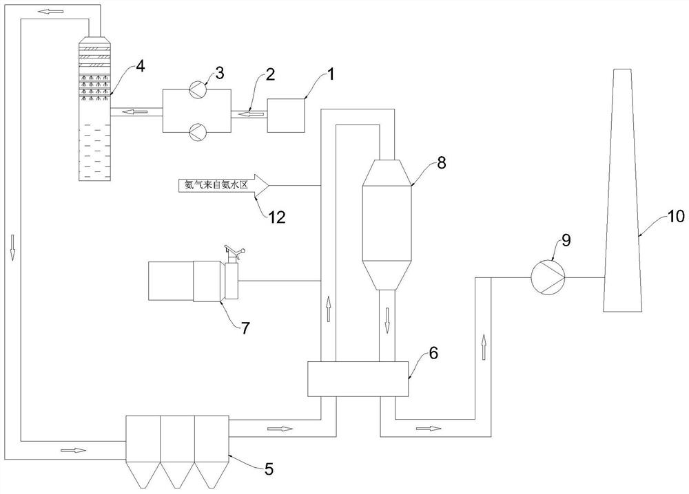
[0024] see figure 1 As shown, a low-temperature SCR denitration system for sintering flue gas described in this embodiment includes a desulfurization tower 4. The flue gas input end of the desulfurization tower 4 introduces the flue gas generated by the sintering machine 1, and the flue gas passes between the desulfurization tower 4 and the sintering machine 1. The gas pipeline 2 is connected, and the main exhaust fan 3 is connected with the flue gas pipeline 2. The main exhaust fan 3 is used to input the flue gas in the flue gas pipeline 2 into the desulfurization tower 4, and the flue gas output end of the desulfurization tower 4 is connected to the dust collector 5. The input end is connected, the flue gas output end of the dust collector 5 is connected with the original flue gas inlet end of the heat exchanger 6, the original flue gas output end of the heat exchanger 6 is connected with the flue gas input end of the low temperature SCR denitration tower 8, and the low tempe...

Embodiment 2

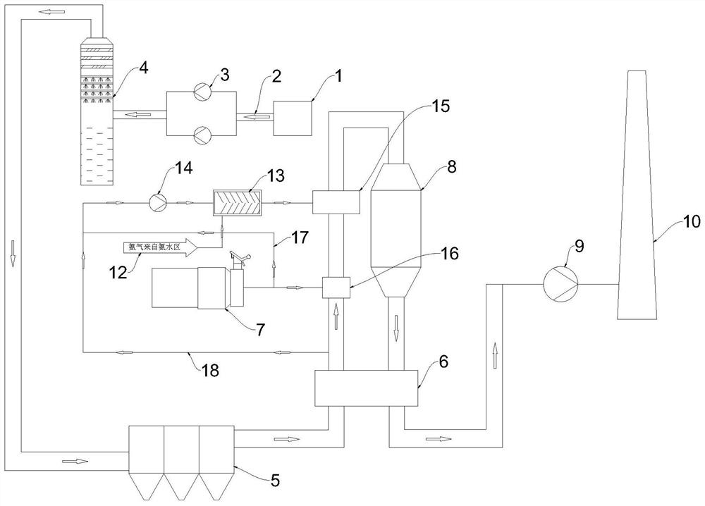
[0034] The catalyst on-line in-situ regeneration system described in this embodiment includes a low-temperature SCR denitration system for sintering flue gas described in Embodiment 1, and the catalyst in the present invention is a low-temperature denitration catalyst.

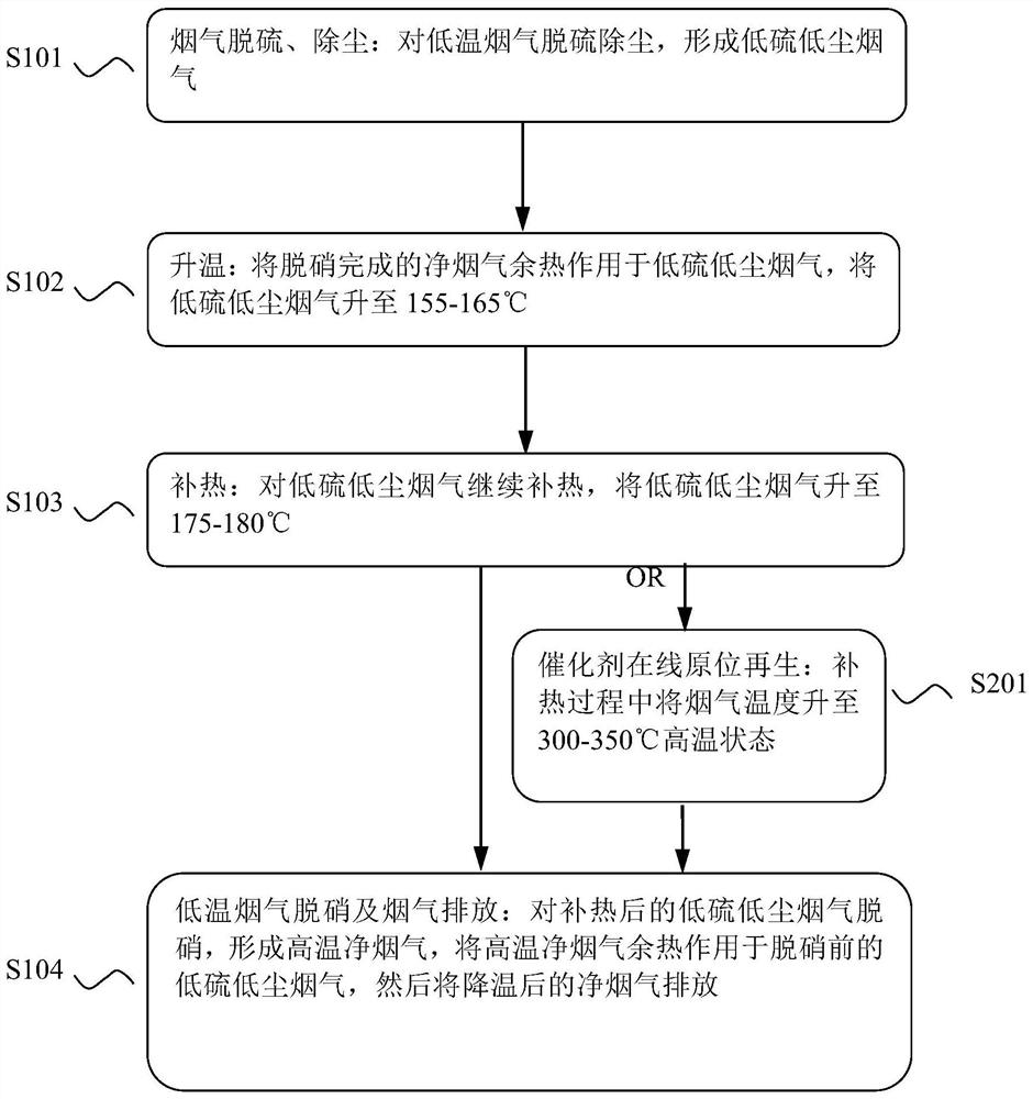
[0035] When the low-temperature SCR denitration system for sintering flue gas is running, when the low-temperature catalyst needs to be regenerated online, there is no need to add additional equipment. It is only necessary to increase the gas consumption through the hot blast stove to increase the temperature of the original flue gas to a high temperature of 300-350 °C. The catalyst is analyzed and regenerated at a high temperature, and the surface active sites are recovered, so that the low-temperature SCR denitration catalyst can be regenerated online in-situ, and the regeneration generally lasts for 1-2 days; at the same time, the first to fifth steps in Example 1 can be repeated. , without affecting the den...


PUM


Abstract

The invention provides a sintering flue gas low-temperature SCR denitration system and a catalyst online in-situ regeneration system, and relates to the technical field of flue gas denitration and catalyst online in-situ regeneration. The low-temperature SCR denitration system comprises a heat exchanger and a hot blast stove; the original flue gas output end of the heat exchanger is connected with the flue gas input end of the low-temperature SCR denitration tower, the flue gas output end of the low-temperature SCR denitration tower is connected with the purified flue gas input end of the heat exchanger, an ammonia gas pipe fixedly penetrates through a front-section flue of the low-temperature SCR denitration tower, and the hot air output end of the hot air furnace fixedly penetrates through the front-section flue of the low-temperature SCR denitration tower. The hot-blast stove hot air output end is positioned at the front section of the ammonia pipe output end By combining the low-temperature SCR denitration system and the catalyst online in-situ regeneration system, when the low-temperature catalyst is subjected to online regeneration, denitration of the low-temperature SCR denitration tower on low-temperature flue gas and online in-situ regeneration of the low-temperature catalyst are not affected, the operation stability of the catalyst is improved, and the energy consumption and the operation cost are reduced.

Description

technical field [0001] The invention relates to the technical field of flue gas denitration and catalyst on-line in-situ regeneration, in particular to a low-temperature SCR denitration system for sintering flue gas and a catalyst on-line in-situ regeneration system. Background technique [0002] The NOx emission control in the sintering flue gas has encountered great difficulties, because the emission temperature of the sintering flue gas is mostly around 130-160 °C, and the working temperature of the denitrification device currently used in the power industry is 300 °C-400 °C. It is difficult for the industry to directly use the medium and high temperature (300℃-400℃) denitration process to control NOx emissions. The huge market demand and increasingly strict environmental emission requirements make it urgent to develop a system suitable for low-temperature SCR denitration of sintering flue gas. [0003] In addition, due to the high SO2 characteristics of sintering flue g...

Claims


Application Information

Patent Timeline
IPC IPC(8): B01D53/86B01D53/88B01D53/56
CPCB01D53/8631B01D53/885B01D2258/0283Y02P10/25
Inventor 訾朝辉郑勇苏龙龙
Owner ANHUI TONGXING ENVIRONMENTAL PROTECTION ENG
Why Eureka
Try Eureka