Separating reacting pulverizer

A pulverizer and reaction technology, used in centrifuges, fuel supply, block/powder fuel preparation, etc., can solve the problems of easy aging of catalysts, low efficiency of pulverizing powder, and unclean selection, and improve equipment Operational efficiency, flue gas emissions are completely environmentally friendly, and the effect of resource recycling is realized

Inactive Publication Date: 2018-01-30
陈久斌
View PDF0 Cites 1 Cited by
  • Summary
  • Abstract
  • Description
  • Claims
  • Application Information

AI Technical Summary

Problems solved by technology

[0016] The current nuclear fuel is mainly selected by a centrifuge, which is too expensive and the selection is not clean, causing environmental pollution and waste of resources.
Nuclear waste and nuclear sewage basically cannot be treated, causing serious environmental hazards
[0017] Existing waste treatment technologies generally use incineration, landfill, etc., and the tail gas treatment after incineration is not clean, causing serious air pollution, and landfill causes land occupation and groundwater pollution
[0018] Existing oil and gas recovery equipment generally has problems such as high cost and incomplete oil and gas recovery
[0019] Existing reactor equipment includes reactors, catalyst reaction tanks or towers, etc., which generally have defects such as slow reaction speed, incomplete reaction, high cost, and easy aging of catalysts.
[0020] Existing boiler equipment, burner equipment, etc. generally have insufficient combustion, especially the burnout rate of coal-fired boilers is only about 80%, resulting in serious energy waste and serious environmental pollution caused by insufficient combustion
[0021] Existing grinding equipment includes pulverizers, Raymond mills, wind-swept mills, etc., which generally have high energy consumption, low grinding powder efficiency, and difficulty in preparing ultra-fine powders.

Method used


Image

  • Separating reacting pulverizer
  • Separating reacting pulverizer
  • Separating reacting pulverizer

Examples


Embodiment Construction

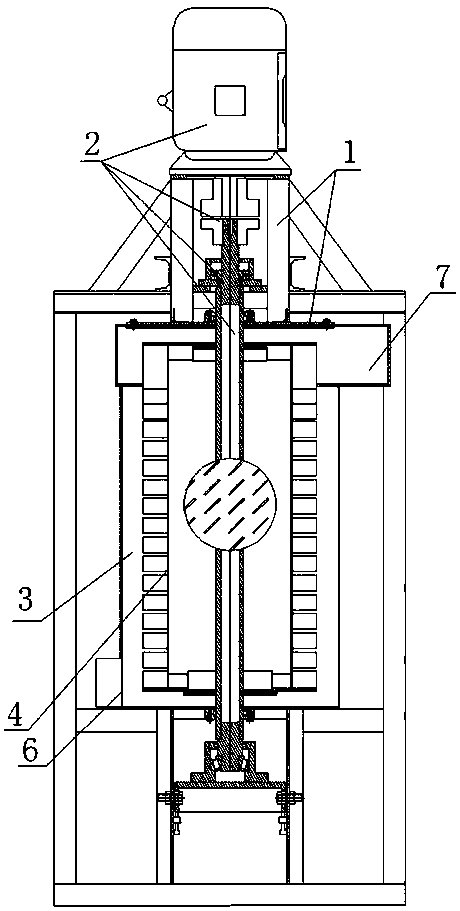
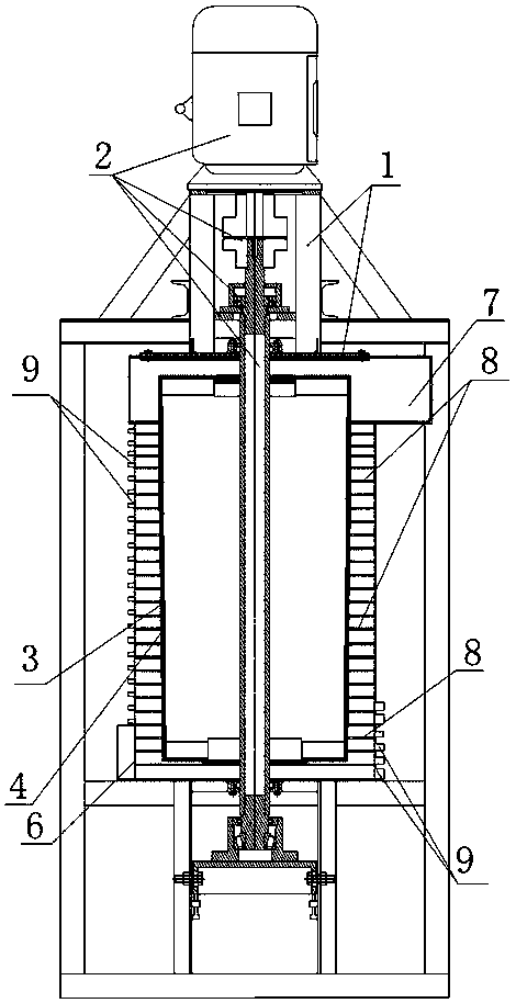
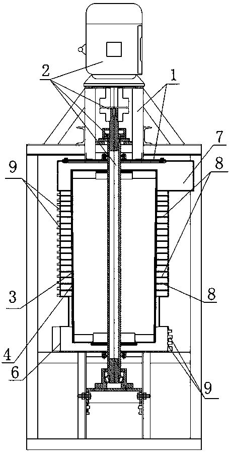
[0065] The main structure of the present invention includes a housing 1 and a transmission device 2, the transmission device 2 is arranged on the housing 1, the housing cavity 3 is arranged in the housing 1, the vortex wheel 4 is arranged in the housing cavity 3, and the vortex wheel 4 is arranged on the outer circumference and the axial direction. A plurality of fluid actuating devices 5 are arranged on each of them, the transmission device 2 is connected with the vortex wheel 4 , the casing chamber inlet 6 is arranged at one end of the casing chamber 3 , and the casing chamber outlet 7 is arranged at the other end of the casing chamber 3 .

[0066] The scope of the casing 1 includes a base, a bracket, a pipe, a casing, and a power device, and each part can be collectively referred to as a casing. The housing 1 can also be integrated with the power device to form an integral housing. The present invention can select different materials to manufacture according to needs, can u...


PUM


Abstract

A separating reacting pulverizer comprises a housing and a transmission device, the transmission device is arranged on the housing, a housing chamber is arranged in the housing, a vortex wheel is arranged in the housing chamber, the transmission device is connected with the vortex wheel, one end of the housing chamber is provided with a housing chamber inlet, and the other end of the housing chamber is provided with a housing chamber outlet. The separating reacting pulverizer is widely applicable to dust removal, desulfurization, denitrification, smoke removal, deodorization, vehicular and marine emission purification, lampblack suction, air purification, oil gas recycling, garbage treatment, nuclear waste treatment, powder separation, mineral separation, sea water desalination, wastewatertreatment, water purification, oil refining, oxygen production, reactors, boilers, combustors, pulverizing equipment and other fields, can provide deep purification for flue gas, can solve air pollution and water pollution, can eliminate haze, and allows water resource shortage, water pollution and environmental pollution to be thoroughly solved. The separating reacting pulverizer is suitable forproducing various powders, including nano powder, can provide low-temperature full combustion for fuels without producing nitric oxides, can provide intra-furnace dry desulfurization and dedusting, and allows a boiler to be completely green.

Description

technical field [0001] The invention relates to separators, centrifuges, sewage treatment, water purification, seawater desalination, marine chemical industry, ore dressing, coal preparation, nuclear fuel selection, nuclear waste treatment, oil refining, oil and gas recovery, garbage treatment, air purification, dust removal, dust collection, Desulfurization, denitrification, oil fume purification, tail gas treatment, black smoke removal, odor removal, oxygen production, air separation extraction, reactor, boiler, burner, grinding and other fields, specifically a separation reaction grinding machine, which can realize The three functions of grinding, chemical reaction and separation can be used alone or in combination. Background technique [0002] Today's environmental pollution mainly includes water pollution, air pollution, etc. Environmental pollution has seriously affected the earth's ecological circle. Atmospheric pollution has seriously affected the earth's ecosphere...

Claims


Application Information

Patent Timeline
Patent Type & Authority Applications(China)
IPC IPC(8): B04B5/12B04B7/02B04B11/00B04B15/00B04B15/02F23K1/00
CPCB02C19/00B04B5/12B04B7/02B04B11/00B04B15/00B04B15/02F23K1/00
Inventor 陈久斌
Owner 陈久斌
Why Eureka
Try Eureka