Flue gas denitrification system

A flue gas and denitrification technology, which is applied in the field of flue gas denitrification system, can solve the problems of affecting the service life of the booster system, increasing the operating cost of the flue gas denitrification system, increasing the manufacturing cost and technical difficulty of the booster system, and achieving the goal of reducing losses Effect

Inactive Publication Date: 2018-12-11
昆山市三维换热器有限公司
View PDF3 Cites 1 Cited by
  • Summary
  • Abstract
  • Description
  • Claims
  • Application Information

AI Technical Summary

Problems solved by technology

[0003] Please refer to the Chinese Utility Model Patent No. 201520986907.x published on May 11, 2016, which discloses a flue gas denitrification system, which includes a boiler, a pyrolysis furnace, and an SCR reactor. The flue gas pipe connects the boiler to the The pyrolysis furnaces are connected together, and a booster system is installed on the flue gas pipeline to transport the high-temperature flue gas in the boiler to the pyrolysis furnace. Due to the high temperature of the boiler flue gas, the requirements for the booster system are very high. As a result, the manufacturing cost and technical difficulty of the supercharging system are increased, and the operating cost of the flue gas denitrification system is increased, and the supercharging system is kept running at high temperature, which affects the service life of the supercharging system

Method used


Image

  • Flue gas denitrification system
  • Flue gas denitrification system

Examples


Embodiment Construction

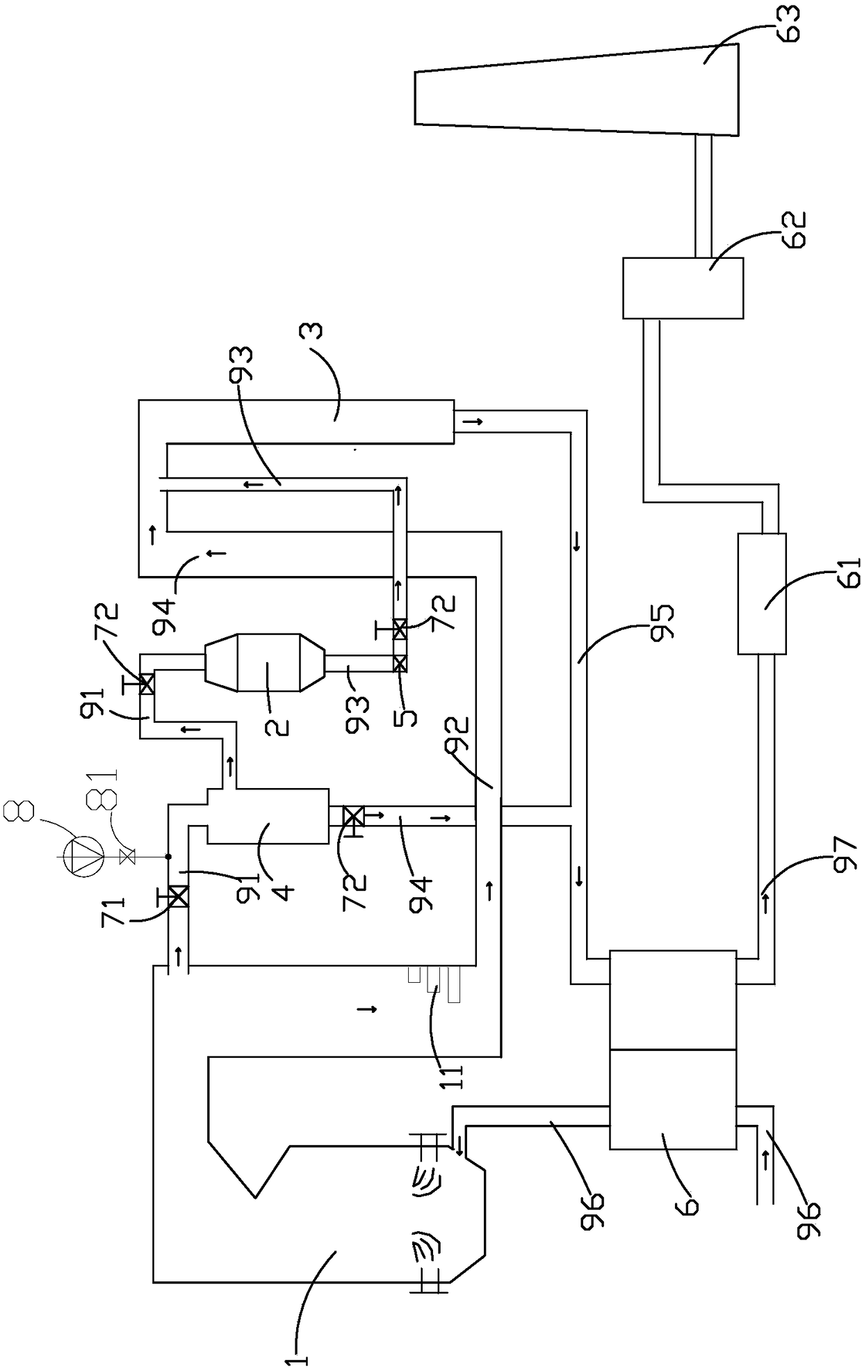
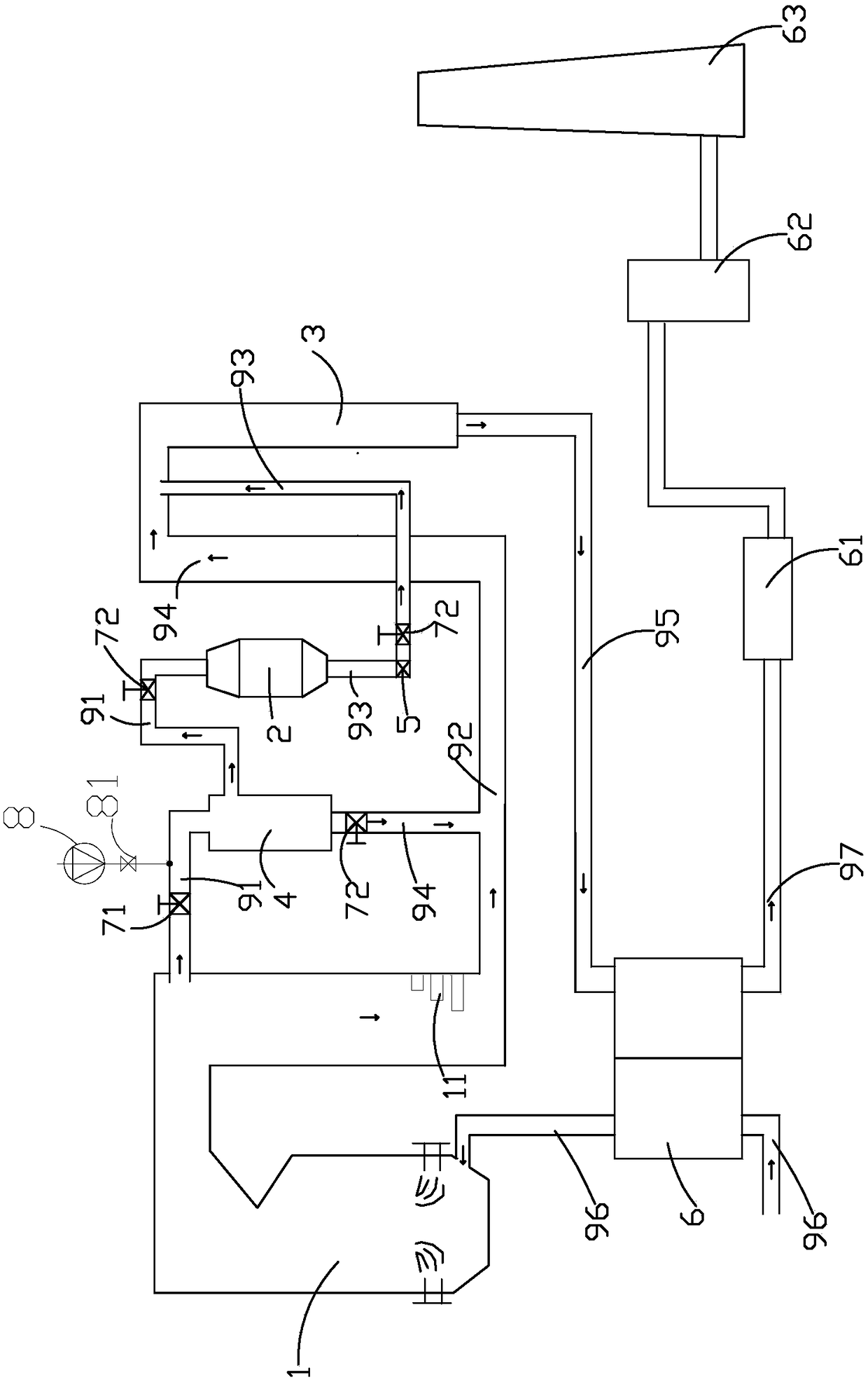
[0019] Such as figure 1 As shown, it is the first embodiment of a flue gas denitrification system involved in the invention, which includes a boiler furnace 1, a pyrolysis mechanism 2, an SCR reactor 3, a dust collector 4, a draft and booster mechanism 5, an air preheating Device 6, main valve 71, multiple air valves 72, cold air system 8 and pipeline system. The boiler furnace 1 is a device for generating high-temperature flue gas.

[0020] The piping system includes a flue gas pipe 91, a furnace flue 92, an air outlet pipe 93, a dust discharge pipe 94, a flue gas discharge pipe 95 and a primary hot air pipe 96; one end of the flue gas pipe 91 is connected to the boiler furnace 1, and the other is One end communicates with the pyrolysis mechanism 2 . In this embodiment, the flue gas pipe 91 is connected to the upper end of the boiler furnace 1, or it can be understood that the place where the flue gas pipe 91 is connected to the boiler furnace is an area that can extract hi...


PUM


Abstract

The invention discloses a flue gas denitrification system. The flue gas denitrification system comprises a boiler hearth, a pyrolysis mechanism, an SCR reactor, a pipeline system and an exhausting pressurizing mechanism, wherein the pyrolysis mechanism, the SCR reactor and the pipeline system are located outside the boiler hearth; one end of a flue gas pipeline is communicated to the boiler hearth, and the other end of the flue gas pipeline is communicated to a pyrolysis mechanism; one end of a hearth flue is communicated to the boiler hearth, and the other end of the hearth flue is communicated to the SCR reactor; an air outlet pipeline is communicated to a hearth flue through the flue gas pipeline; and the exhausting pressurizing mechanism is connected between the pyrolysis mechanism andthe SCR reactor and is communicated to the air outlet pipeline. The exhausting pressurizing mechanism is arranged at the lower end of the pyrolysis mechanism, and pressurized high-temperature flue gas is introduced into the SCR reactor, so that the flue gas denitrification is realized; and compared with the prior art, the flue gas denitrification system has the advantages that the defect of an over-high temperature of the exhausting pressurizing mechanism is improved, and the service life of the system is not influenced.

Description

【Technical field】 [0001] The invention relates to a flue gas denitration system for a coal-fired power plant, in particular to a pyrolysis and reaction flue gas denitrification system. 【Background technique】 [0002] Nitrogen oxides (NOx) in the flue gas of coal-fired power plants are one of the main air pollutants. At present, the selective catalytic reduction technology (SCR) is mainly used to control the emission of nitrogen oxides in the flue gas, that is, the use of reducing agents to selectively It reacts positively with the nitrogen oxides in the flue gas and generates non-toxic and pollution-free nitrogen (N 2 ) and water (H 2 O), to achieve the purpose of denitrification and environmental protection. The commonly used reducing agents in the denitrification system are liquid ammonia, ammonia water and urea solution. Urea is selected as the reducing agent, which has the characteristics of high safety, wide range of sources, easy transportation and storage, and has b...

Claims


Application Information

Patent Timeline
Patent Type & Authority Applications(China)
IPC IPC(8): B01D53/86B01D53/56F23J15/02
CPCB01D53/8625B01D2258/0283F23J15/02F23J2215/10
Inventor 顾安生陆华
Owner 昆山市三维换热器有限公司
Why Eureka
Try Eureka