
Light homogenizer and laser equipment

A technology of laser equipment and homogenizer, which is applied in the field of lasers, can solve problems such as fiber damage, fiber end face damage, and quartz fiber damage, and achieve the effects of uniform light intensity, reduced damage, and convenient operation

Pending Publication Date: 2022-08-02
广东迪光医学科技有限公司
View PDF0 Cites 0 Cited by
  • Summary
  • Abstract
  • Description
  • Claims
  • Application Information

AI Technical Summary

Problems solved by technology

Laser ablation technology is a technology that guides laser pulses to intravascular lesion tissue through optical fiber bundles for ablation. Although this technology is safe and reliable, there are still some problems. For example, high-energy laser pulses are easy to cause damage to quartz optical fibers. It can be divided into two aspects. On the one hand, when the laser pulse is coupled from the laser to the fiber bundle, the damage to the end face of the fiber is caused due to the energy density of the light exceeding the damage threshold of the quartz glass; on the other hand, when the laser pulse is transmitted in the fiber, due to The self-interference phenomenon caused by coherence produces damage inside the fiber
Another example is that the spot area is small and the energy distribution of the spot is uneven, which affects the application of laser ablation technology in medicine.
Moreover, the existing uniform light technology is not mature enough, and the uniform light effect cannot meet the needs of current laser technology, and there is still the problem of uneven energy distribution of the spot, and under normal circumstances, it is easy to cause problems such as damage to waveguide materials by ultraviolet band lasers.

Method used

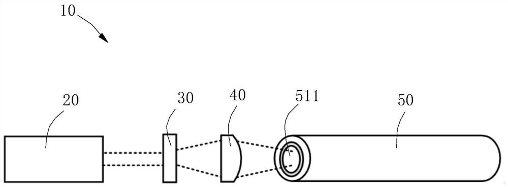
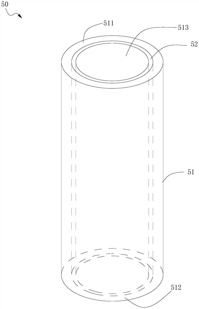
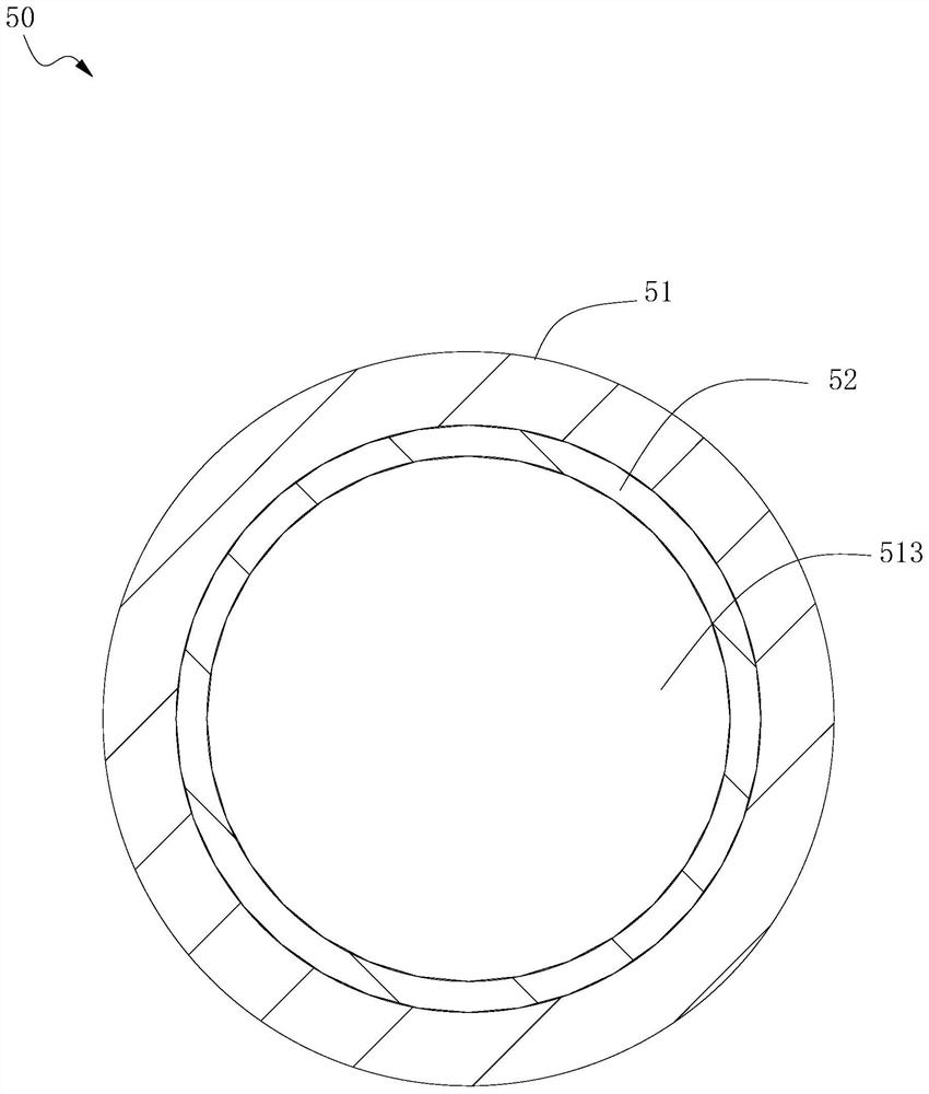

Image

  • Light homogenizer and laser equipment
  • Light homogenizer and laser equipment
  • Light homogenizer and laser equipment

Examples


Embodiment Construction

[0022] In order to make the above objects, features and advantages of the present invention more clearly understood, the specific embodiments of the present invention will be described in detail below with reference to the accompanying drawings. In the following description, numerous specific details are set forth in order to provide a thorough understanding of the present invention. However, the present invention can be implemented in many other ways different from those described herein, and those skilled in the art can make similar improvements without departing from the connotation of the present invention. Therefore, the present invention is not limited by the specific embodiments disclosed below.

[0023] In the description of the present invention, it should be understood that the terms "center", "longitudinal", "lateral", "length", "width", "thickness", "upper", "lower", "front", " Back, Left, Right, Vertical, Horizontal, Top, Bottom, Inner, Outer, Clockwise, Countercl...


PUM

PropertyMeasurementUnit
reflectanceaaaaaaaaaa

Abstract

The invention relates to a light homogenizer for laser pulse and laser equipment, the light homogenizer comprises a body and a reflecting layer, the body is provided with a hollow channel for penetration of the laser pulse, the reflecting layer covers the inner wall of the hollow channel, and the inner diameter of the hollow channel is not smaller than the diameter of an input laser spot. The body is provided with an input end face and an output end face, the input end face is used for receiving a laser pulse, and the output end face is used for transmitting the laser pulse after dodging. One port of the hollow channel is located on the input end face, and the other port is located on the output end face. By adopting the dodging device provided by the invention, the laser pulse can excite more than two high-order modes, the light intensity homogenization of the cross section of the light beam is realized, the light spot area is increased, the light spot energy distribution uniformity is improved, the coherence of the laser pulse is destroyed, the damage of the high-energy laser pulse to the optical fiber is reduced, and the optical fiber quality is improved. The dodging device is simple in structure and convenient to use.

Description

technical field [0001] The invention relates to the field of laser technology, in particular to a light homogenizer and laser equipment. Background technique [0002] With the development and progress of laser science, laser equipment has become more and more widely used in medicine. Among them, laser ablation technology has received extensive attention and application in the industry due to its easy operation and high safety. Laser ablation technology is a technology that guides laser pulses through fiber bundles to intravascular diseased tissue for ablation. Although this technology is safe and reliable, there are still some problems. For example, high-energy laser pulses can easily damage silica fibers. The damage mechanism It can be divided into two aspects. On the one hand, when the laser pulse is coupled from the laser to the fiber bundle, the fiber end face is damaged because the energy density of the light exceeds the damage threshold of the quartz glass; on the othe...

Claims


Application Information

Patent Timeline
Patent Type & Authority Applications(China)
IPC IPC(8): G02B27/09A61B18/20
CPCG02B27/0977G02B27/0938A61B18/201A61B2018/2035
Inventor 钟晨陶茜吴寒李力
Owner 广东迪光医学科技有限公司
Learn More