High-voltage pulse generator based on solid-state switch

A solid-state switch and high-voltage pulse technology, which is applied in the direction of pulse generation, pulse technology, and electric pulse generation, can solve problems such as strong electromagnetic interference, large overall power consumption, overvoltage, and overcurrent sensitivity, and achieve electromagnetic interference and power consumption. Low, increase the output frequency, the effect of excellent output index

Pending Publication Date: 2022-08-02
XJ POWER CO LTD +1
View PDF0 Cites 0 Cited by
  • Summary
  • Abstract
  • Description
  • Claims
  • Application Information

AI Technical Summary

Problems solved by technology

[0003] Traditional high-voltage pulse generators use gas switches or thyratrons as switching devices. Due to device reasons, the output pulse frequency is generally below 1Hz; and the output pulse is instantaneous, resulting in strong electromagnetic interference, which is harmful to auxiliary power, triggering and control. The anti-interference requirements of the unit are high and the overall power consumption is large
Compared with traditional switches, high-voltage solid-state switches have the advantages of fast turn-on speed, high operating frequency, simple control method, and small electromagnetic interference. However, compared with traditional switches, they are more sensitive to overvoltage and overcurrent, and the turn-on speed reaches nanosecond voltage levels. High solid-state switching has high power consumption and poor stability, which is not conducive to long-term and reliable use of the device

Method used


Image

  • High-voltage pulse generator based on solid-state switch
  • High-voltage pulse generator based on solid-state switch

Examples


specific Embodiment

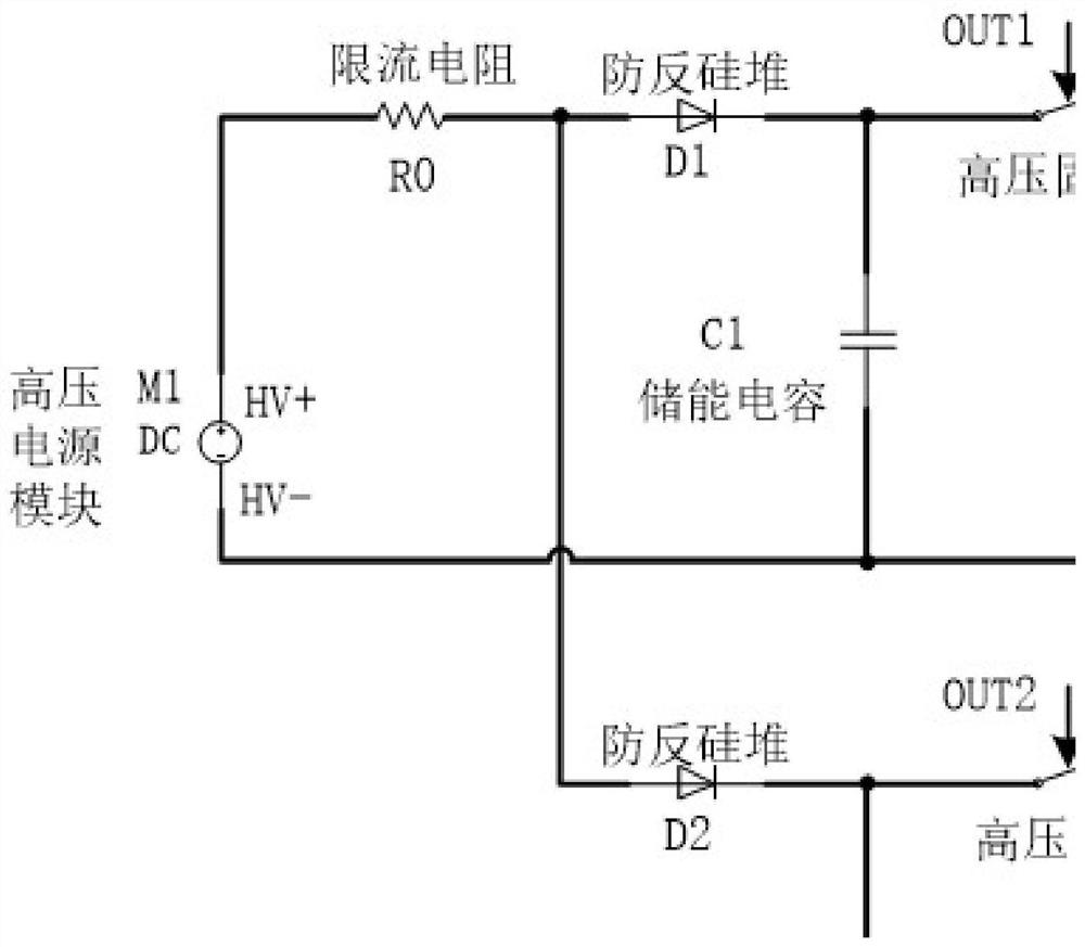
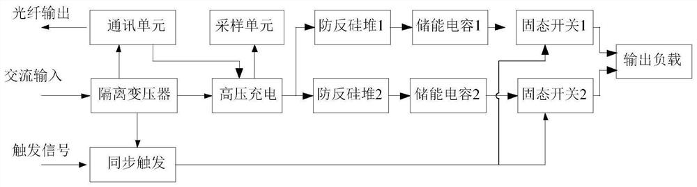
[0033] like figure 1 Shown is an implementation circuit of a solid-state switch-based high-voltage pulse generator provided in this embodiment, figure 2 This is an implementation block diagram of the complete pulse generator provided in this embodiment.

[0034] figure 1 The middle and upper part is the principle of the main circuit circuit. M1 is a high-voltage power supply module, R0 is a current limiting resistor, D1 and D2 are anti-anti-anti-anti-silicon stacks with anti-anti-reverse inhibition, M1 respectively charges the energy storage capacitors C1 and C2 through R0, during the charging process, D1 and D2 are in positive Conduction state; Q1 and Q2 are two high-voltage solid-state switches. The high-voltage solid-state switch used in this embodiment is a mature product. It is realized based on MOS transistors in series and parallel. The turn-on and turn-off time can reach within 50ns but the voltage level is low; OUT1 and OUT2 are the driving signals of two high-vol...


PUM


Abstract

A high-voltage pulse generator based on a solid-state switch comprises a high-voltage charging unit, an energy storage unit, a synchronous triggering unit and a pulse output unit, the pulse output unit comprises a first pulse output subunit and a second pulse output subunit, the first pulse output subunit is switched on and off through the high-voltage solid-state switch Q1, and the second pulse output subunit is switched on and off through the energy storage unit. The first pulse output subunit is switched on and off through a high-voltage solid-state switch Q1, the second pulse output subunit is switched on and off through a high-voltage solid-state switch Q2, the high-voltage charging unit is used for charging the energy storage unit, the first energy storage subunit is used for providing pulse voltage U1 for the first pulse output subunit, and the second energy storage subunit is used for providing pulse voltage U2 for the second pulse output subunit. And the pulse voltage value output by the pulse output unit is the sum of the voltage values of the U1 and the U2. The output frequency of the whole pulse generator is improved while nanosecond pulse output is achieved, meanwhile, the voltage is distributed to the two pulse output subunits, the insulation grade and power consumption in the generator are reduced, and the stability of the generator is improved.

Description

technical field [0001] The invention relates to the field of high-voltage pulse generators, in particular to a high-voltage pulse generator based on solid state switches. Background technique [0002] High-voltage pulses refer to pulse voltages with pulse voltages ranging from hundreds of volts to tens of thousands of volts and pulse widths in microseconds or milliseconds. They are generally generated by high-voltage pulse generators and are used in applications that require high-voltage pulses, such as the triggering of pulsed xenon lamps, High voltage electrostatic generator, laser drive power supply, particle acceleration, etc. [0003] Traditional high-voltage pulse generators use gas switches or thyratrons as switching devices. Due to device reasons, the output pulse frequency is generally below 1Hz; and at the moment of output pulses, the generated electromagnetic interference is strong, which affects the auxiliary power supply, triggering and control. The anti-interf...

Claims


Application Information

Patent Timeline
Patent Type & Authority Applications(China)
IPC IPC(8): H03K3/537
CPCH03K3/537
Inventor 李振国张君甘江华龙蛟刘辉勇胡建超杨国杰许丽娜张省赵莹莹陈璐明李鹏军皇利杰田勤宁文斌袁攀孙双峰杨海涛彭佳
Owner XJ POWER CO LTD
Why Eureka
Try Eureka