Frequency Synthesizer

a frequency synthesizer and frequency technology, applied in oscillator generators, pulse automatic control, electrical apparatus, etc., can solve the problems of increasing the number of parts, increasing the noise, and complicated circuit construction, so as to enhance the output frequency and enhance the frequency entraining range. , the effect of small nois

Active Publication Date: 2009-07-02
NIHON DEMPA KOGYO CO LTD
View PDF4 Cites 5 Cited by
  • Summary
  • Abstract
  • Description
  • Claims
  • Application Information

AI Technical Summary

Benefits of technology

[0050]Accordingly, When PLL is locked, the output frequency of the voltage-controlled oscillation unit is adjusted to a set frequency. However, by merely pre-calculating the frequency of the vector when the output frequency of the voltage-controlled oscillation unit is equal to the set value, the output frequency can set although the PLL is one-stage PLL. Therefore, the frequency can be finely set over a broad band area with little noise. For example, the voltage-controlled oscillation unit of several hundreds MHz can be set every 1 Hz or every frequency pitch lower than 1 Hz, and thus an extremely epoch-making frequency synthesize can be obtained.
[0051]In the present invention, a first constant is integrated by an integrating circuit portion and output as a control voltage of the voltage-controlled oscillation unit while the output frequency from the voltage-controlled oscillation unit is small and thus there is a large difference between the output frequency and the set frequency, thereby enhancing the output frequency. After the difference between them is substantially equal to zero, the integration is stopped, and then after the difference between them is large, a second constant is integrated by the integration circuit portion. Therefore, the frequency entraining range is broad, and even when the frequency of the voltage-controlled oscillation unit is fluctuated or the frequency is varied due to the temperature characteristic or the like, the frequency entrainment can be performed. Therefore, a stable operation can be obtained.
[0052]Furthermore, according to a second invention, the probability that switching is carried out in the vicinity of the center value in the digital / analog converter of the feedback means for fine adjustment, so that the number of switches to be switched at the same time is reduced and glitch noise can be reduced.

Problems solved by technology

However, if the frequency division ratio is excessively increased, noise becomes large due to elongation of a delay occurring in a loop, and actually the upper limit of N is equal to about 1000.
However, in this case, PLL must be constructed with respect to each synthesizing circuit for synthesizing frequencies, and thus there is a problem that the circuit construction is complicated, the number of parts is increased and noise is increased.
Therefore, the inventor of this application has developed a novel type frequency synthesizer which can finely set the frequency over a broad band by adopting a novel construction which is completely different from the conventional frequency synthesizers on principle, however, has run into trouble in that the frequency entraining range is narrow and the frequency entrainment cannot be surely performed in consideration of the dispersion of products of the voltage-controlled oscillation unit, the temperature characteristic, etc.
Furthermore, this frequency synthesizer comprises analog circuits and digital circuits, and has a problem that noise caused by simultaneous switching of many switching elements in a digital / analog converter must be suppressed.

Method used


Image

  • Frequency Synthesizer
  • Frequency Synthesizer
  • Frequency Synthesizer

Examples


Embodiment Construction

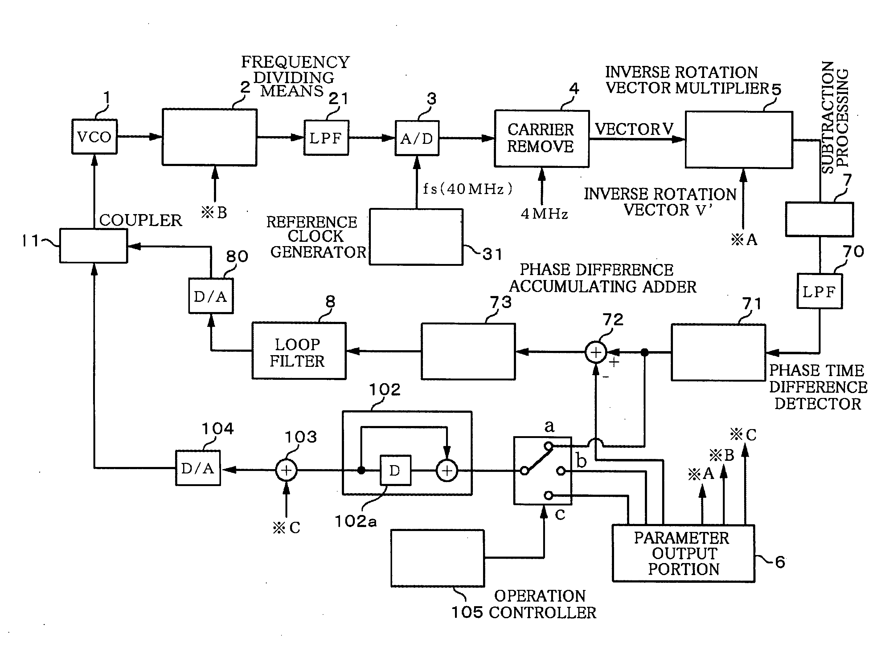
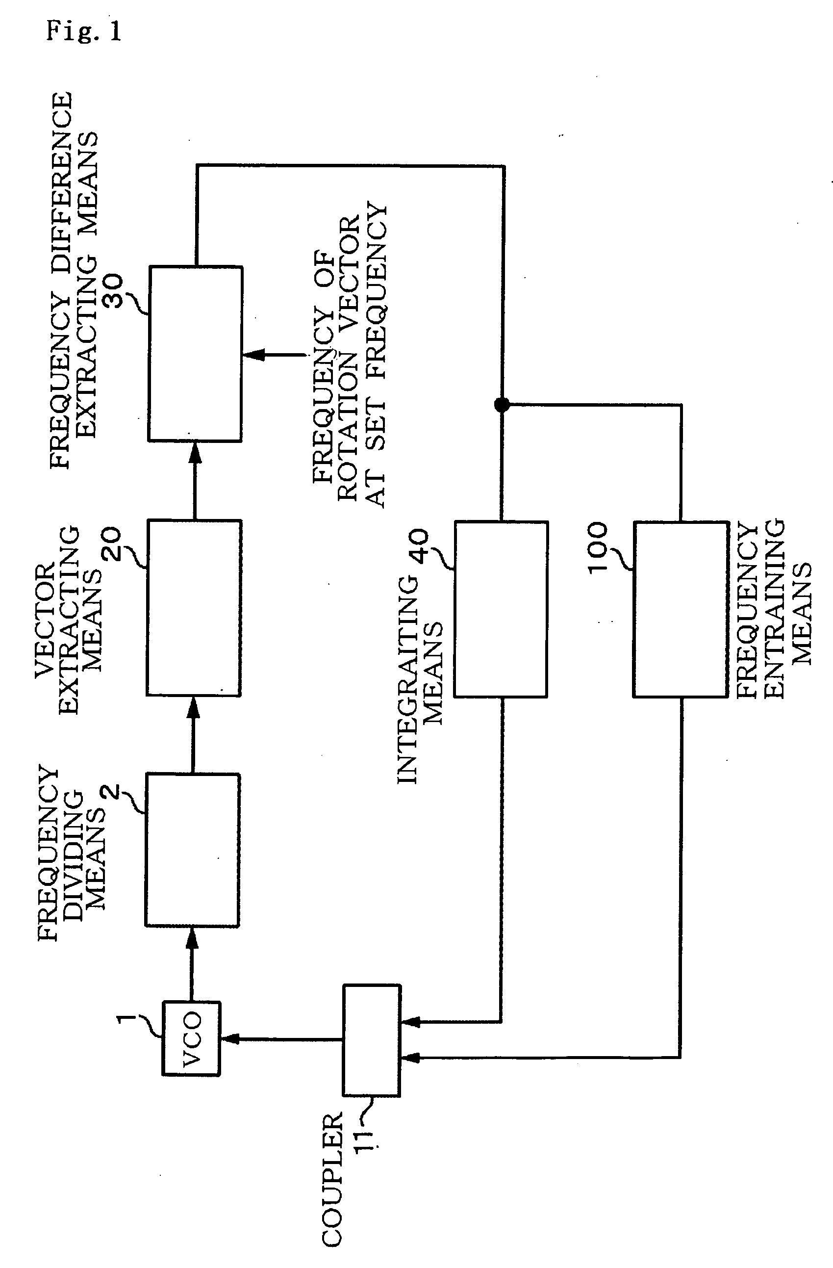
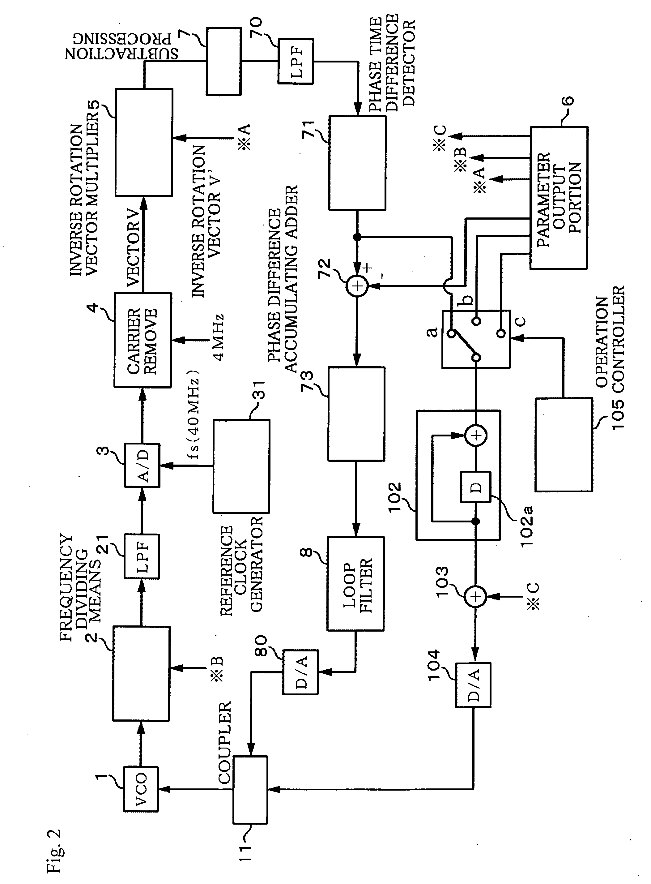
[0069]A frequency synthesizer according to the present invention is operated on the basis of a novel principle, and thus the operation principle of the present invention will be first briefly described with reference to FIG. 1. In FIG. 1, 1 represents a voltage-controlled oscillation unit as a voltage-controlled oscillation unit, and it outputs a frequency signal as a rectangular wave whose frequency corresponds to a supply voltage passed from a voltage output portion 11 through a first adder 12. The frequency signal from the voltage-controlled oscillator 1 is frequency-divided to 1 / N (N represents an integer) by frequency dividing means 2, converted to a sinusoidal wave and converted to a digital signal. In this case, the following description is confined to only the description that a vector rotating at the frequency (speed) corresponding to the frequency of the frequency signal is extracted by vector extracting means 20.

[0070]Frequency difference extracting means at the rear stag...


PUM


Abstract

An object of the present invention provides a frequency synthesizer having a broad frequency entraining range which can finely set a frequency over a broad band by a novel principle.
As s specific solving means, a sinusoidal signal of an output frequency of a voltage-controlled oscillator is subjected to orthogonal detection, a vector rotating at the differential frequency (speed) between the output frequency and the frequency of the frequency signal used for the detection is created, and the frequency of a vector when the output frequency of the voltage-controlled oscillator is equal to a set value is calculated in advance. The voltage signal corresponding to the difference between the frequency of the vector and the calculated frequency is fed back to the voltage-controlled oscillator when the voltage-controlled oscillator is driven, and PLL is formed so that the difference is equal to zero. Accordingly, the output frequency of the voltage-controlled oscillator is adjusted to the set frequency when PLL is locked. After the difference between both the frequencies is increased after PLL is locked, the set value is integrated by the integrating circuit portion and added to the control voltage.

Description

TECHNICAL FIELD[0001]The present invention relates to a frequency synthesizer for obtaining an oscillation output having a desired frequency.BACKGROUND ART[0002]A frequency synthesizer to which PLL (Phase Locked Loop) is applied as one of standard signal generators is known. As shown in FIG. 12, in the frequency synthesizer, a voltage-controlled oscillator 201 is subjected to 1 / N frequency division by a frequency divider 202 and the frequency-division output is input to one input terminal of a phase comparator 203. In addition, an oscillation output of a crystal oscillator 204 as a reference signal generator is subjected to 1 / M frequency-division by a frequency divider 200 and the frequency-division output is input to the other input terminal of the phase comparator 203. The comparison signal therebetween is fed back to the voltage-controlled oscillator 201 through a loop filter 205, thereby constructing PLL (for example, Patent Document 1). When PLL is locked, the frequency fvco of...

Claims


Application Information

Patent Timeline
Patent Type & Authority Applications(United States)
IPC IPC(8): H03B21/00
CPCH03L7/085H03L7/091H03L7/10H03L2207/12H03L7/185H03L7/187H03L2207/06H03L7/18H03L7/113H03L7/107
Inventor KOBATA, TSUKASASHIOBARA, TSUYOSHIAKAIKE, KAZUOTSUKAMOTO, NOBUO
Owner NIHON DEMPA KOGYO CO LTD
Why Eureka
Try Eureka