Quantitative feeding device for metal powder machining

A technology of quantitative feeding and metal powder, applied in the field of metal powder processing, can solve the problems affecting the effect of compact forming of parts, and achieve the effect of enhancing the effect of back blowing

Active Publication Date: 2022-08-09
徐州威德金属制品有限公司
View PDF13 Cites 2 Cited by
  • Summary
  • Abstract
  • Description
  • Claims
  • Application Information

AI Technical Summary

Problems solved by technology

[0003] When using powder metallurgy technology to produce parts with complex shapes, it is necessary to feed metal powder into the green compact through a feeding device, and the powder particles in the green compact contact each other through the action of pressing force, friction, extrusion, displacement and deformation, and finally However, during the metal powder feeding process, it was found that the metal powder easily accumulates in the feeding chamber and forms blockages of various structures such as agglomerates, plugs, and arches, and the metal powder fed into the compact is too Too much or too little will affect the effect of parts compacting

Method used


Image

  • Quantitative feeding device for metal powder machining
  • Quantitative feeding device for metal powder machining
  • Quantitative feeding device for metal powder machining

Examples


Embodiment 1

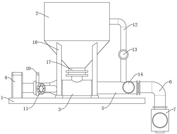
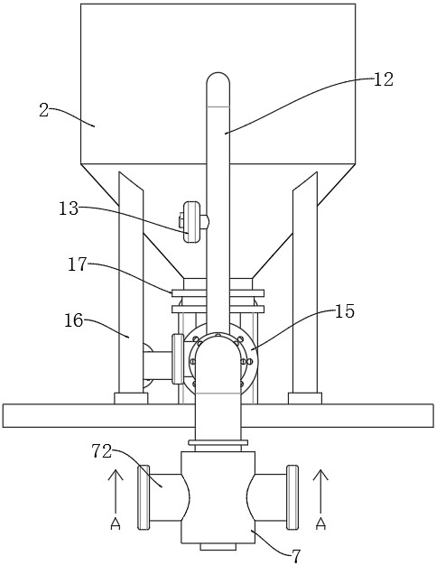
[0032] like Figure 1 to Figure 4 As shown in the figure, a quantitative feeding device for metal powder processing according to the present invention includes a silo 2 installed on the bottom plate 1, and also includes a feeding pipe 3 arranged under the silo 2. One end of the feeding pipe 3 is provided with There is an air pump 4, the other end of the feeding pipe 3 is provided with a feeding pipe 5, the end of the feeding pipe 5 away from the feeding pipe 3 is connected with the arc-shaped pipe 6, and the end of the arc-shaped pipe 6 away from the feeding pipe 5 is provided with an upper Material cavity 7;

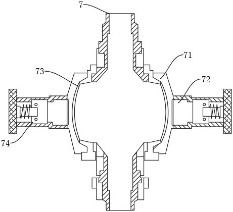
[0033] The feeding cavity 7 includes an inner wall and an outer wall, and there is a space between the inner wall and the outer wall for installing the external expansion joint 71. The outer wall of the feeding cavity 7 is provided with an external expansion cavity 72. The outer wall is connected with the outer expansion joint 71 through, and the inner wall of the feed...

Embodiment 2

[0052] The difference from Example 1 is that:

[0053] like Figure 5 to Figure 6 As shown, the inner wall of the feeding cavity 7 is composed of two sets of upper and lower shrink films 73, and the upper and lower sets of shrink films 73 are connected by a ring-shaped connecting block. The upper and lower closed spaces are formed into two upper and lower closed spaces and correspond to the upper and lower two groups of shrink films 73 respectively, and both upper and lower closed spaces are provided with a cam 751 and a sliding rod 752. The two cams 751 are connected by the connecting shaft 9, and the upper The length of the sliding rod 752 is smaller than the length of the sliding rod 752 below.

[0054] In actual operation, it is found that the metal powder accumulation density inside the feeding cavity 7 is also different. Since the interior of the feeding cavity 7 near the lower outlet is closest to the external environment, when the moisture in the external environment ...


PUM


Abstract

The invention relates to the technical field of metal powder processing, in particular to a quantitative feeding device for metal powder processing, which comprises a stock bin mounted on a bottom plate and further comprises a feeding pipe arranged below the stock bin, an air pump is arranged at one end of the feeding pipe, a conveying pipe is arranged at the other end of the feeding pipe, and one end, far away from the feeding pipe, of the conveying pipe is connected with an arc-shaped pipe. A feeding cavity is formed in the end, away from the conveying pipe, of the arc-shaped pipe and comprises an inner wall and an outer wall, a gap is formed between the inner wall and the outer wall and used for installing an external expansion connector, an external expansion cavity is formed in the outer wall of the feeding cavity and penetrates through the outer wall of the feeding cavity to be connected with the external expansion connector in a penetrating mode, and the inner wall of the feeding cavity is of a smooth flexible shrinkage film structure. The shrink film, the external expansion connector and the external expansion cavity jointly form a closed space, a piston and a pushing mechanism connected with the piston are arranged in the external expansion cavity, metal powder can be prevented from being blocked in the feeding cavity, and quantitative feeding can be achieved so that it can be guaranteed that the amount of the metal powder in a pressed blank is within a reasonable range.

Description

technical field [0001] The invention relates to the technical field of metal powder processing, in particular to a quantitative feeding device for metal powder processing. Background technique [0002] Powder metallurgy is a metal product formed by pressing and sintering metal powder as raw material. It has the advantages of energy saving, material saving, near-net shape, environmental protection, economy and high efficiency. It can effectively use raw materials to manufacture complex materials that are difficult to cast by traditional processes. Parts, and suitable for mass production, it is highly valued by the industry. [0003] When using powder metallurgy technology to produce parts with complex shapes, the metal powder needs to be fed into the compact through the feeding device, and the powder particles are in contact with each other, rubbed, and squeezed in the compact through the action of pressing force. Displacement and deformation, and finally Forming, but in the...

Claims


Application Information

Patent Timeline
Patent Type & Authority Applications(China)
IPC IPC(8): B22F3/00
CPCB22F3/004Y02P10/25
Inventor 于红波于江海
Owner 徐州威德金属制品有限公司
Why Eureka
Try Eureka