Glass discharging system for hollow glass production

A glass and hollow technology, applied in the field of glass unloading system, can solve the problems of insufficient unloading efficiency of glass stacking, and achieve the effect of saving control steps, improving position accuracy and improving efficiency

Pending Publication Date: 2022-08-09
安徽名特玻璃有限公司
View PDF1 Cites 1 Cited by
  • Summary
  • Abstract
  • Description
  • Claims
  • Application Information

AI Technical Summary

Problems solved by technology

[0005] The object of the present invention is to address the deficiencies of the prior art, to provide a glass unloading system for insulating glass production, through the carrying parts such as electric suction cups arranged in groups on the carriage conveying track, to realize the carrying on the conveying track The department transports the glass twice to the

Method used


Image

  • Glass discharging system for hollow glass production
  • Glass discharging system for hollow glass production
  • Glass discharging system for hollow glass production

Examples


Example Embodiment

[0065] Example 1

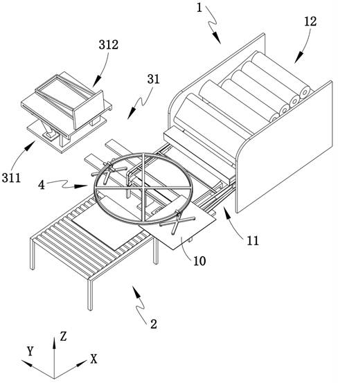
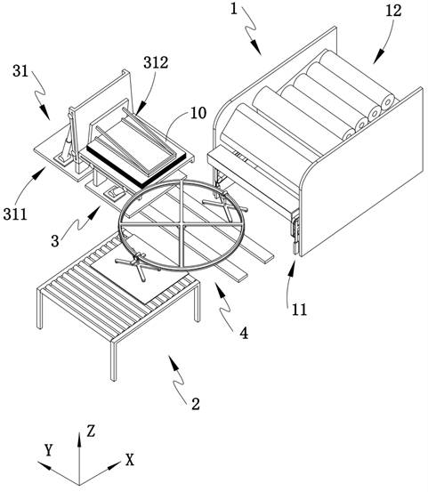
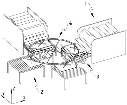
[0066] like Figure 1-5 As shown, the present embodiment provides a glass unloading system for the production of insulating glass, including a paper laying machine 1, and also includes:

[0067] The roller table unit 2, the roller table unit 2 used for conveying the glass 10 to the paper laying machine 1 is arranged on one side of the paper feeding end of the paper laying machine 1;

[0068] a packaging stand 3, for carrying the glass 10, is arranged between the roller table unit 2 and the layer 1; and

[0069] The stacking unit 4, which stacks the glass 10 on the roller table unit 2 to the stacking unit 4 on the packaging rack 3 is arranged between the roller table unit 2 and the packaging rack 3;

[0070] The stacking unit 4 includes:

[0071] Bracket 41, a conveying track 42 is fixed on the bracket 41, and the conveying track 42 passes above the packaging stand 3 and the roller table unit 2;

[0072] Transporting assemblies 43, at least one group of t...

Example Embodiment

[0101] Embodiment 2

[0102] like Figure 1-3 , 9-11, in which the same or corresponding components as in the first embodiment are given the corresponding reference numerals as in the first embodiment. For the sake of brevity, only the differences from the first embodiment are described below. The difference between the second embodiment and the first embodiment is:

[0103] The paper laying machine 1 includes:

[0104] The pulling mechanism 11, the pulling mechanism 11 for guiding the spacer paper to the surface of the stacked glass 10 is arranged on both sides of the packaging platform 3 and is connected to the paper laying machine 1 in a driving connection;

[0105] The paper feeding mechanism 12, the paper feeding mechanism 12 for supplementing the spacer paper in the paper laying machine 1 is fixed above the paper laying machine 1; and

[0106] The lifting assembly 13 is fixed under the traction mechanism 11 and used to adjust the height of the traction mechanism 11 . ...

Example Embodiment

[0120] Embodiment 3

[0121] like Figure 1-3 As shown, the same or corresponding components as those in the first embodiment are given the corresponding reference numerals as in the first embodiment. For the sake of brevity, only the points of difference from the first embodiment are described below. The difference between the third embodiment and the first embodiment is:

[0122] Also includes a transfer assembly 31 for transferring the stacked glass 10, and the transfer assembly 31 is fixed on the bottom of the packaging platform 3;

[0123] The transfer assembly 31 includes a turning part 311 for adjusting the posture of the packaging platform 3 and a loading part 312 for receiving the packaging stack glass 10 .

[0124] In the present embodiment, after the glass 10 on the packaging rack 3 is stacked to the capacity of one packaging unit, the inverting part 311 is installed, for example, on the hydraulic rod group and the sliding table at the bottom of the packaging rack...


PUM


Abstract

The invention provides a glass discharging system for hollow glass production. The glass discharging system comprises a paper laying machine, a roller way unit, a packaging rack and a stacking unit. Grouped carrying parts in the stacking unit are located on a conveying rail above the roller way unit and a conveying rail above the packaging rack correspondingly, a conveying assembly enables the carrying parts above the roller way unit to move grabbed glass to the packaging rack, and meanwhile the carrying parts above the packaging rack are reset to the roller way unit by the conveying assembly after glass stacking is completed. According to the glass stacking device disclosed by the invention, through the carrying parts, such as the electric suction cups, arranged on the conveying track of the bracket in groups, the carrying parts on the conveying track are used for transporting glass twice to the packaging rack for stacking in the process of completing single-time circulating movement; the glass stacking efficiency is improved, the electrostatic adsorption procedure is replaced, and the problem that the glass stacking and unloading efficiency is insufficient is solved.

Description

technical field [0001] The invention relates to the technical field of glass deep processing, in particular to a glass unloading system used for the production of insulating glass. Background technique [0002] After the glass is processed, it needs to be packaged and stored. In order to save the volume occupied by the glass, the manufacturer usually stacks the glass. When the glass is stored in a humid environment, the glass surface will be broken and mildewed; A capillary phenomenon occurs, and the dust particles or moisture in the inhaled air react chemically, causing the two pieces of glass to stick together, and it is difficult to separate them during use. Therefore, the glass is isolated by laying spacer paper; The paper laying machine used is usually arranged at the end of the production line, and a manipulator or robot grabs the glass and places it on the paper laying platform for paper laying. [0003] Chinese Patent Application No. 201710591992.3 discloses a high-...

Claims


Application Information

Patent Timeline
IPC IPC(8): B65G49/06B65B35/50B65B23/20B65B35/18B65B35/22B65B61/20
CPCB65G49/061B65G49/068B65B35/50B65B23/20B65B35/18B65B35/22B65B61/207Y02P40/57
Inventor 李井高周鑫炎邢朋
Owner 安徽名特玻璃有限公司
Why Eureka
Try Eureka