CO2 emission monitoring method and monitoring system

A technology of emissions and CO2, applied in radio wave measurement systems, satellite radio beacon positioning systems, measurement devices, etc., can solve the problem of long dynamic update cycle of CO2 emissions, large uncertainty of CO2 emissions, and inability to reduce emissions Provide data support and other issues to achieve the effect of overcoming data uncertainty, overcoming non-random missing, and simplifying data types

Active Publication Date: 2022-08-09
STATE GRID SICHUAN ELECTRIC POWER CORP ELECTRIC POWER RES INST
View PDF5 Cites 2 Cited by
  • Summary
  • Abstract
  • Description
  • Claims
  • Application Information

AI Technical Summary

Problems solved by technology

[0006] The technical problem to be solved by the present invention is that in the prior art, a top-down method is used to infer CO 2 emissions, the accuracy of the statistical data cannot be guaranteed, resulting in the final calculated CO 2 Uncertainty in emissions is large, and CO based on this method 2 The dynamic update cycle of emissions is long, and it is impossible to provide real-time data support for emission reduction work

Method used


Image

  • CO2 emission monitoring method and monitoring system
  • CO2 emission monitoring method and monitoring system
  • CO2 emission monitoring method and monitoring system

Examples


Embodiment 1

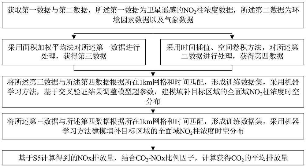
[0060] This embodiment discloses a CO 2 Emissions monitoring methods, such as figure 1 As shown, the method steps include:

[0061] S1: Obtain first data and second data, the first data is satellite remote sensing NO 2 Column concentration data, the second data is environmental factor data and meteorological data; the tropospheric monitoring instrument (TROPOMI)-NO carried on "Sentinel-5P" was obtained from public data sources 2 Tropospheric column concentration data, boundary layer height, elevation, population density, road density, land use type, normalized vegetation index and meteorological data (pressure, temperature, east-west wind speed, north-south wind speed, humidity, evaporation), built environment large datasets.

[0062] In this embodiment, the environmental factor data includes boundary layer height, altitude data, population density, road density, land use type data, and normalized vegetation index. The meteorological data includes air pressure data, temper...

Embodiment 2

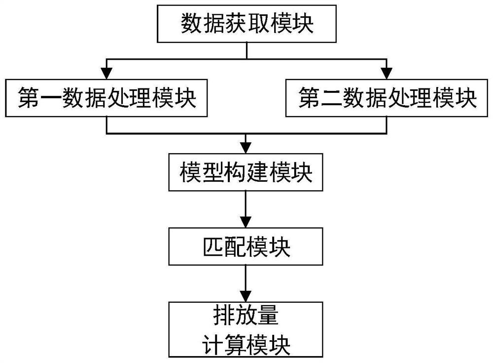
[0105] This embodiment discloses a CO 2 Emission estimation system, this example is to realize CO as in Example 1 2 Emissions extrapolation methods, such as figure 2 As shown, it includes a data acquisition module, a first data processing module, a second data processing module, a model building module, a matching module and an emission calculation module;

[0106] The data acquisition module is used to acquire the first data and the second data, and the first data is the satellite remote sensing nitrogen dioxide tropospheric column concentration (abbreviated as NO). 2 column concentration) data, the second data is environmental factor data and meteorological data;

[0107] the first data processing module, configured to process the first data by using the area weighted average method to obtain third data;

[0108] The second data processing module is configured to process the second data by adopting methods such as time interpolation and spatial convolution to obtain four...


PUM


Abstract

The invention discloses a CO2 emission monitoring method and monitoring system. The method comprises the following steps: acquiring first data and second data; processing the first data by adopting an area weighted average method to obtain third data; processing the second data by adopting a time interpolation and spatial convolution method to obtain fourth data; matching the third data with the fourth data according to the 1km grid and time to form a training data set, and modeling by adopting a machine learning method to fill the comprehensive domain NO2 column concentration space-time distribution of the target area; matching the space-time distribution of the filled NO2 column concentration with the wind speed and the wind direction, and calculating by adopting a linear density fitting method to obtain the average NOx emission in each wind direction; the NOx emission amount is combined with a CO2-NOx scaling factor, and the CO2 emission amount is obtained; the method has the beneficial effects that the calculation accuracy of the CO2 emission amount and the dynamic updating frequency are improved, and real-time data support is provided for emission reduction and carbon reduction work.

Description

technical field [0001] The present invention relates to CO 2 The technical field of emissions, specifically, involves a CO 2 Emission monitoring method and monitoring system. Background technique [0002] Controlling greenhouse gas emissions and coping with climate change are major challenges for sustainable human development in the 21st century. Accurate calculation of CO 2 Emissions are the basis for promoting carbon reduction work, and can provide a basis for carbon emission statistics and accounting. Currently for CO 2 The calculation of emissions is mostly based on bottom-up methods based on statistics and surveys, that is, statistical accounting of emissions from various emission sources is carried out through relevant data such as industrial production, economic development and energy consumption. [0003] The "China High Spatial Resolution Emission Grid Database" refers to the international mainstream bottom-up spatialization method, and allocates space from the ...

Claims


Application Information

Patent Timeline
Patent Type & Authority Applications(China)
IPC IPC(8): G01N33/00G01W1/02G01S19/39
CPCG01N33/004G01W1/02G01S19/39Y02P90/845
Inventor 陈玉敏唐伟张凌浩徐厚东魏阳刘洪利李赋欣刘雪原庞博赵瑞祥
Owner STATE GRID SICHUAN ELECTRIC POWER CORP ELECTRIC POWER RES INST
Why Eureka
Try Eureka