Magnetostatic wave element and its manufacturing method

A manufacturing method and magnetostatic technology, applied in electrical components, waveguide-type devices, chemical instruments and methods, etc., can solve the problems of deteriorating the characteristics of magnetostatic wave components, and achieve the effect of excellent frequency characteristics

Inactive Publication Date: 2004-06-16
MURATA MFG CO LTD
View PDF0 Cites 0 Cited by
  • Summary
  • Abstract
  • Description
  • Claims
  • Application Information

AI Technical Summary

Problems solved by technology

In practice, for an input signal with an electric power not greater than Psh, although it is best not to suppress the output signal, this phenomenon actually occurs, thereby deteriorating the characteristics of the magnetostatic wave element

Method used


Image

  • Magnetostatic wave element and its manufacturing method
  • Magnetostatic wave element and its manufacturing method
  • Magnetostatic wave element and its manufacturing method

Examples


example 1

[0037] Table 1

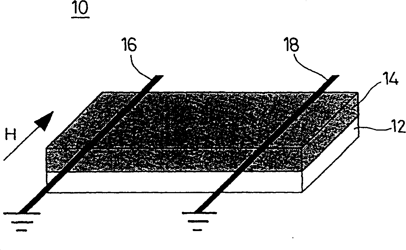
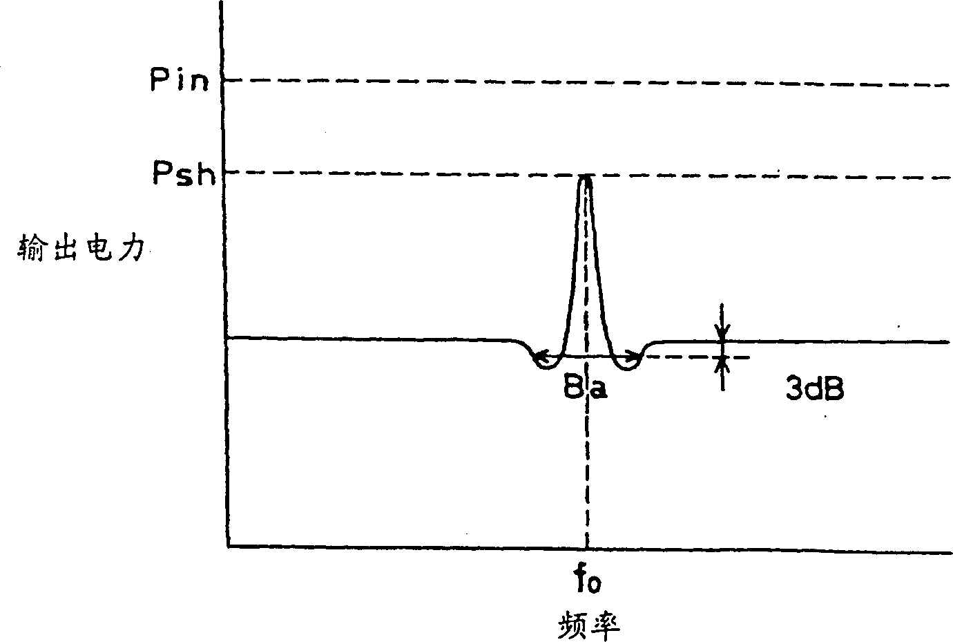
[0038] Two microstrip lines are formed substantially parallel to each other at a specific distance on the single crystal YIG film thus prepared, and the figure 1The magnetostatic wave element shown. In the measurement, Ba was 1.4MHz, wherein the frequency fo of the input signal was set to 1.5GHz, the input electric power Pin was set to -17dBm, and the applied magnetic field H was set to 8000A / m. The value Ba=1.4MHz obtained by this magnetostatic wave element is excellent because it is compatible with image 3 Compared with the value of , it can be seen that this value is only 1 / 5 to 1 / 2 of the value obtained by using lead-containing single crystal YIG film, and the film is made of PbO-B 2 o 3 It is made of raw material melting liquid.

example 2

[0040] With MoO 3 : K 2 O:Y 2 o 3 : Fe 2 o 3 =39.1: 37.5: 16.9: 6.5 mole ratio, so that the solvent component MoO 3 with K 2 O and Fe as components of YIG 2 o 3 with Y 2 o 3 Mix it up, put this mixture into a platinum crucible as a raw material melting liquid, melt at 1200°C for 12 hours, cool to 1100°C, and bring it into contact with a GGG substrate with a diameter of 52mm for 2 hours to form a film on it with a thickness of about 5 μm The composition of single crystal YIG films was analyzed by inductively coupled plasma emission spectrometry. As a result, molybdenum, potassium and platinum were detected as single crystal components Fe 2 o 3 with Y 2 o 3 Other ingredients are listed in Table 2. However, their content is extremely small, not exceeding 40 ppm by weight. Of course, lead was detected in the single crystal film.

[0041] Table 2

Impurity elements

Impurity content

(weight ppm)

molybdenum

40

Lithium...


PUM


Abstract

A magnetostatic wave element, having a narrow bandwidth range Ba in which an output signal is suppressed centering around frequency fo by 3 dB or more for an input signal with an electric power of Psh or less at a frequency fo, is obtained using substantially Pb-free materials.

Description

technical field [0001] The present invention relates to magnetostatic wave elements. In particular, it relates to a magnetostatic wave element which converts microwaves, for example, into magnetostatic waves propagating through a single-crystal magnetic garnet film and then converts them into microwave output, and a manufacturing method thereof. Background technique [0002] figure 1 An example of magnetostatic wave device technology related to the present invention is shown. The magnetostatic wave element 10 comprises a nonmagnetic substrate 12, for example, a gadolinium gallium garnet (GGG) substrate is used as the nonmagnetic substrate 12, and a single crystal magnetic garnet film 14 is formed thereon, and yttrium iron garnet (YIG) can be used film as the single-crystal magnetic garnet film 14 . In addition, two microstrip lines 16 and 18 are formed on the single crystal magnetic garnet film 14 at a specific pitch. The microstrip line 16 is used for signal input, and ...

Claims


Application Information

Patent Timeline
Patent Type & Authority Patents(China)
IPC IPC(8): C30B19/02H01F10/24H01P1/215H01P3/08H03H2/00H03H9/25
CPCY10T428/11H03H2/001H01P3/08
Inventor 高木隆藤野优
Owner MURATA MFG CO LTD
Why Eureka
Try Eureka