Position phase type ultra-high-difinition long focal iris

A super-resolution, phase-type technology, applied in apertures, optics, cameras, etc., can solve the problems of low energy utilization, complex aperture amplitude and phase distribution, and difficult production of apertures, achieving wide application prospects and easy mass production. and replication, the effect of high diffraction efficiency

Inactive Publication Date: 2005-01-26
SHANGHAI INST OF OPTICS & FINE MECHANICS CHINESE ACAD OF SCI
View PDF0 Cites 1 Cited by
  • Summary
  • Abstract
  • Description
  • Claims
  • Application Information

AI Technical Summary

Problems solved by technology

Although the phase type super-resolution aperture has also been studied in the prior art (see [1].Hideo ANDO, Phase-Shifting Apodizer of Three or More Portions, Jpn.J.Appl.Phys.Vol.31 pp.557-567 , 1992.[2].Tasso R.M.Sales andG.Michael Morris, Diffractive superresolution elements, J.Opt.Soc.Am.A / Vol.14pp1637-1646, 1997), but did not use this type of aperture for axial optimization to Work on obtaining long focal depth; some studies on extending focal depth (see [3]. J. Ojeda-Castaneda, P. Andres, and A. Díaz, Annular apodizers for low sensitivity to defocus and to spherical aberrration, Opt .Lett.Vol.11, No.8 pp487-489, 1986.[4].J.Ojeda-Casta eda, L.R.Berriel-Valdos, and E.Montes, Spatial filter for increasing the depth of focus, Opt.Lett.Vol.10, No.11, pp520-522, 1985.), but due to its result is from the expected intensity Therefore, the amplitude and phase distribution of the required aperture is very complicated. Such an aperture is difficult to manufacture, and its energy utilization rate is low due to the existence of amplitude modulation.

Method used


Image

  • Position phase type ultra-high-difinition long focal iris
  • Position phase type ultra-high-difinition long focal iris
  • Position phase type ultra-high-difinition long focal iris

Examples


Embodiment Construction

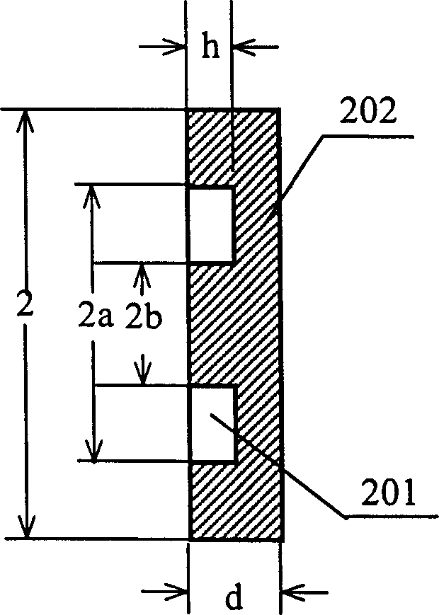
[0018] We optimized the axial light intensity distribution for different b values, and gave a series of b and a values. Different values ​​of b and a correspond to different focal depth extensions. Tables 1 and 2 give a series of b, a, focal depth extension multiples, half-width ratio, side lobes relative to the main spot intensity, Sterby.

[0019] b

a

Depth of focus extension factor t

Half-width ratio

Sterby

Relative intensity of side lobe

0

0

1

1

1

0.01

0

0.4

2.34

0.829

0.449

0.23

0.05

0.41

2.43

0.824

0.434

0.235

0.1

0.42

2.57

0.817

0.410

0.238

0.15

0.45

2.57

0.816

0.396

0.222

0.2

0.48

2.63

0.813

0.369

0.203

[0020] 0.25

0.52

...


PUM


Abstract

A position-phase type iris with long focus depth and ultra-high difinition features that the concave ring and convex ring, which are concentric with iris, are made on a parallel plate made of transparent material. After light beam passes through the iris with concave and convex rings, a retardation between said light beam and the light beam passing through other position is half of wavelenglth, so axial peaks are cancelled to elongate focus depth by more than 3 times and radical edges are cancelled to increase difinition. It can be used in microelectronic processing, photoetching and scan microscopic focusing or imaging system.

Description

Technical field [0001] The invention is a phase-type super-resolution diaphragm for extending the focal depth of a focused beam. It can be widely used in optical imaging systems and beam focusing systems. Background technique [0002] In microelectronics processing, photolithography, scanning microscopy, and high-density optical disk storage, it is hoped to obtain a smaller focusing spot, which requires a shorter laser wavelength and a focusing objective with a higher numerical aperture, because the focused beam The half-height width can be expressed as D = λ 2 NA , Where λ is the wavelength of the incident laser beam and NA is the numerical aperture of the focusing objective. Super-resolution technology (that is, the technology beyond the diffraction limit) is also one of the methods commonly used to shrink the recording point. It is by placing a diffraction or refraction dia...

Claims


Application Information

Patent Timeline
IPC IPC(8): G02B26/06G02B27/58G03B9/02
Inventor 王海凤陈仲裕干福熹
Owner SHANGHAI INST OF OPTICS & FINE MECHANICS CHINESE ACAD OF SCI
Why Eureka
Try Eureka