On-line laser energy and light power density space-time distribution measuring system

A technology of optical power density and laser energy, which is applied in photometry, optical radiation measurement, measuring devices, etc., can solve the problem that the time distribution of optical power density cannot be measured, the time distribution of optical power density cannot be measured, and cannot be measured online, etc. problem, to achieve the effect of ensuring time resolution, ensuring spatial resolution, and ensuring accuracy

Inactive Publication Date: 2005-09-14
NORTHWEST INST OF NUCLEAR TECH
View PDF0 Cites 0 Cited by
  • Summary
  • Abstract
  • Description
  • Claims
  • Application Information

AI Technical Summary

Problems solved by technology

[0007] The object of the present invention is to provide an online laser energy and optical power density time-space distribution measurement system, which solves the problem that the background technology can only measure the total energy value of the laser and the distribution of the optical power density in space, and cannot measure the optical power density in time. The distribution on the surface, or the time distribution of the optical power density cannot be measured; it cannot be measured online; there are many factors that affect the measurement results; the technical problem of low measurement accuracy

Method used


Image

  • On-line laser energy and light power density space-time distribution measuring system
  • On-line laser energy and light power density space-time distribution measuring system
  • On-line laser energy and light power density space-time distribution measuring system

Examples


Embodiment Construction

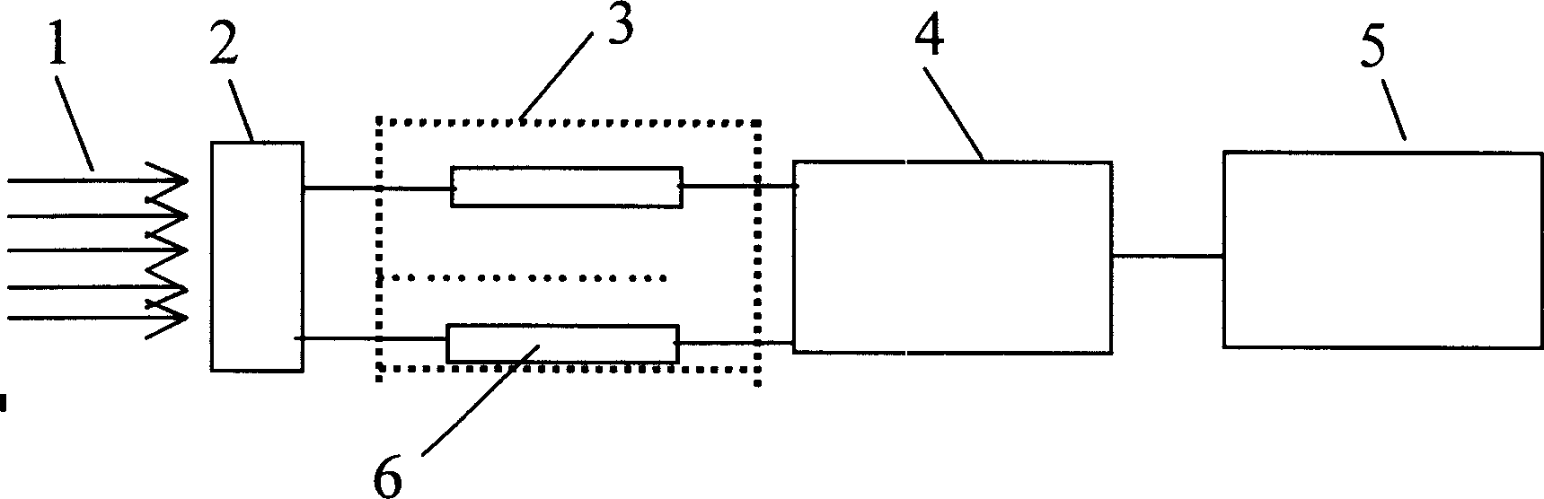
[0035] see figure 1 , the present invention mainly includes an optical sampler 2, an optical detector array 3, a multi-channel data acquisition card 4, and a data processing computer 5. The strong laser light 1 is coupled into the photodetector array 3 after passing through the photodetector 2, and the photodetector array 3 is composed of hundreds of photodetectors 6. The change in the amplitude of the output electrical signal of the photodetector array 3 can reflect the change of the laser light power incident on the optical sampler 2, and the multi-channel data acquisition card 4 collects and records the output signal of each photodetector 6, and then passes The data processing computer 5 processes the measurement results, that is, obtains the distribution of the optical power density of the laser light in time and space, and can calculate the total energy value.

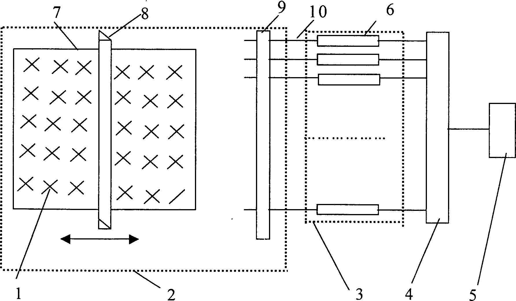
[0036] see figure 2 , The optical sampler 2 mainly includes a frame 7, an optical knife 8, an optical fiber ...


PUM


Abstract

There is kind of measuring system of on-line mode high-energy laser energy and the time-space distribution of the light power density. This system mainly consists of the light sampler, the detector, array, the multi-channel data acquisition card and the data processing computer. This system can on line measure out the change of the light power density of the high-energy laser with the time and space, and the total energy values can also be gained by calculating. This system specially adapts to the infrared wave band, continuous wave, high energy laser, such as the deuterium-fluorin laser, the oxygen iodine laser, etc, and these laser have advantages of large facular area, short irritation time, and high output energy and power density, and it also adapts to the high power density continuous wave laser, such as the carbon-dioxide laser, the YAG laser, etc.

Description

technical field [0001] The invention relates to an online laser energy and optical power density time-space distribution measurement system, in particular to an online measurement system for large-area high-energy laser energy and optical power density time-space distribution. Background technique [0002] Existing methods for measuring high-energy laser energy and optical power density distribution mainly include energy ablation method, target spot scattering measurement method, heat absorption detection method and so on. [0003] The energy ablation method is to let the laser irradiate the ablated object, usually plexiglass, calculate the total energy by measuring the mass change of the ablated object before and after laser irradiation, and roughly obtain the power density of the spot by measuring the ablation trace distributed. The main disadvantage of this method is that it can only measure the total energy value of the laser and the distribution of optical power densit...

Claims


Application Information

Patent Timeline
Patent Type & Authority Patents(China)
IPC IPC(8): G01J1/00G01J1/42
Inventor 陈绍武王群书叶锡生刘福华冯国斌杨鹏翎
Owner NORTHWEST INST OF NUCLEAR TECH
Why Eureka
Try Eureka