
Modular atomic force microscope

An atomic force microscope and modular technology, applied in scanning probe microscopy, instruments, surface/boundary effects, etc., can solve problems such as poor linearity, inconvenient adjustment and replacement, and decreased resonance frequency of scanners, etc., to achieve Effect of High Resonance Frequency

Inactive Publication Date: 2006-06-14
SHANGHAI INST OF OPTICS & FINE MECHANICS CHINESE ACAD OF SCI +1
View PDF1 Cites 1 Cited by
  • Summary
  • Abstract
  • Description
  • Claims
  • Application Information

AI Technical Summary

Problems solved by technology

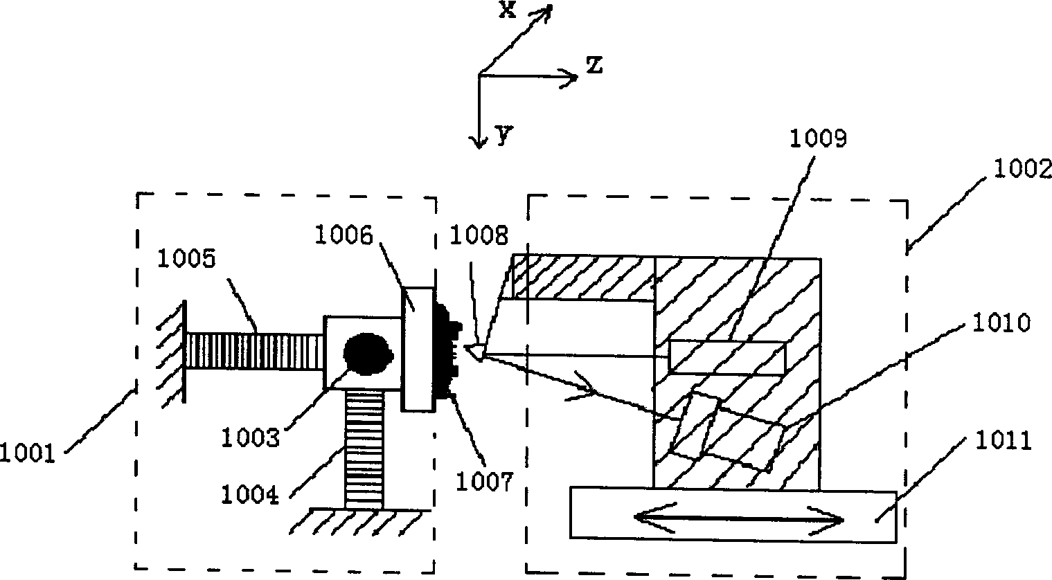
[0004] (1) This technology uses the method of scanning samples, which is only suitable for small sample detection. If the sample placed at the end of the scanner is heavy, it will lead to a decrease in the resonance frequency of the scanner and affect the performance of the atomic force microscope.
[0005] (2) The laser and the position sensitive element are integrated in the photoelectric detection system 1002, which is inconvenient to adjust and replace. It is almost impossible to change the above device into an atomic force microscope with a scanning needle tip
[0006] (3) It is impossible to add an optical microscope, and it is impossible to observe the sample and the micro-cantilever in real time from the micron level, and it is inconvenient to adjust the laser focus on the top of the micro-cantilever
[0007] (4) The sample stage does not have a rough adjustment device in the xy direction, so it is not possible to select the area to be scanned at the micron level
[0008] (5) The scanning and feedback device is composed of three piezoelectric ceramics from the xyz direction or a piezoelectric ceramic tube. These two scanners cannot guarantee the orthogonality of the movement in the three directions of xyz, and the linearity is not good. it is good

Method used


Image

  • Modular atomic force microscope
  • Modular atomic force microscope
  • Modular atomic force microscope

Examples


Embodiment 1

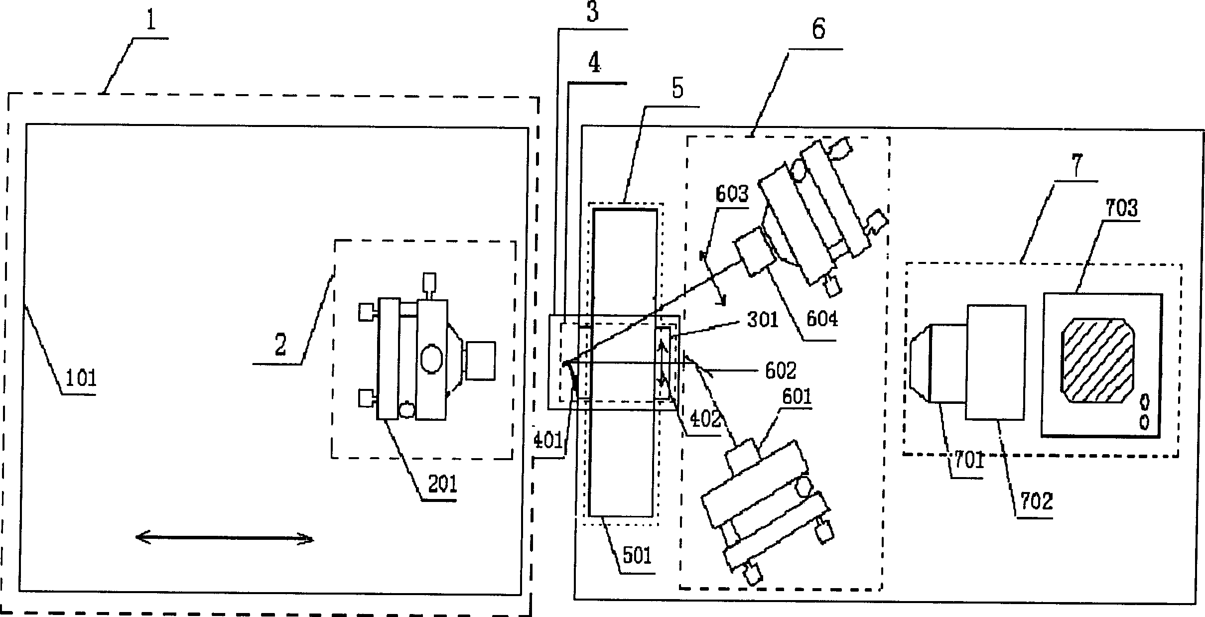
[0027]Embodiment 1 is a horizontal needle tip scanning atomic force microscope. The stepper motor 101 of module 1 adopts the M-405.DG linear displacement platform of PI Company, and its one-way repeatability accuracy is 200nm; As a rough positioning device for the sample, it can adjust the tilt, elevation and movement of the sample in the three directions of xyz; module 3 is the z-direction scanner 301, which uses the P-753.11C linear PZT platform actuator of PI company, The telescopic length is 0.012mm, and the unloaded resonant frequency is 5.6KHz; module 4 includes a microcantilever needle tip 401 with a horizontal tilt of 15 degrees and a focusing lens 402 with a focal length of 20mm, and module 4 is fixed on module 3; module 5 is an xy-direction scanner 501 adopts the P-734.2Cl type device of PI company, the scanning range is 0.1mm*0.1mm, the center of which is a 5cm*5cm light hole, and the no-load resonance frequency is 500Hz. Module 3 is fixed on module 5 and scans in ...

Embodiment 2

[0028] The principle of embodiment 2 is shown as image 3 As shown, using the above-mentioned modules, only the fifth module 5 is fixed on the first module 1, the sample is placed on the scanner of the fifth module 5, and the atomic force microscope with sample scanning tip feedback is formed by removing the second module. The microscope can be a reflection type in which the illumination light is irradiated from the top of the sample, or a projection type in which the illumination light is irradiated from the bottom of the sample, because the scanner of the module 5 has a light hole.

Embodiment 3

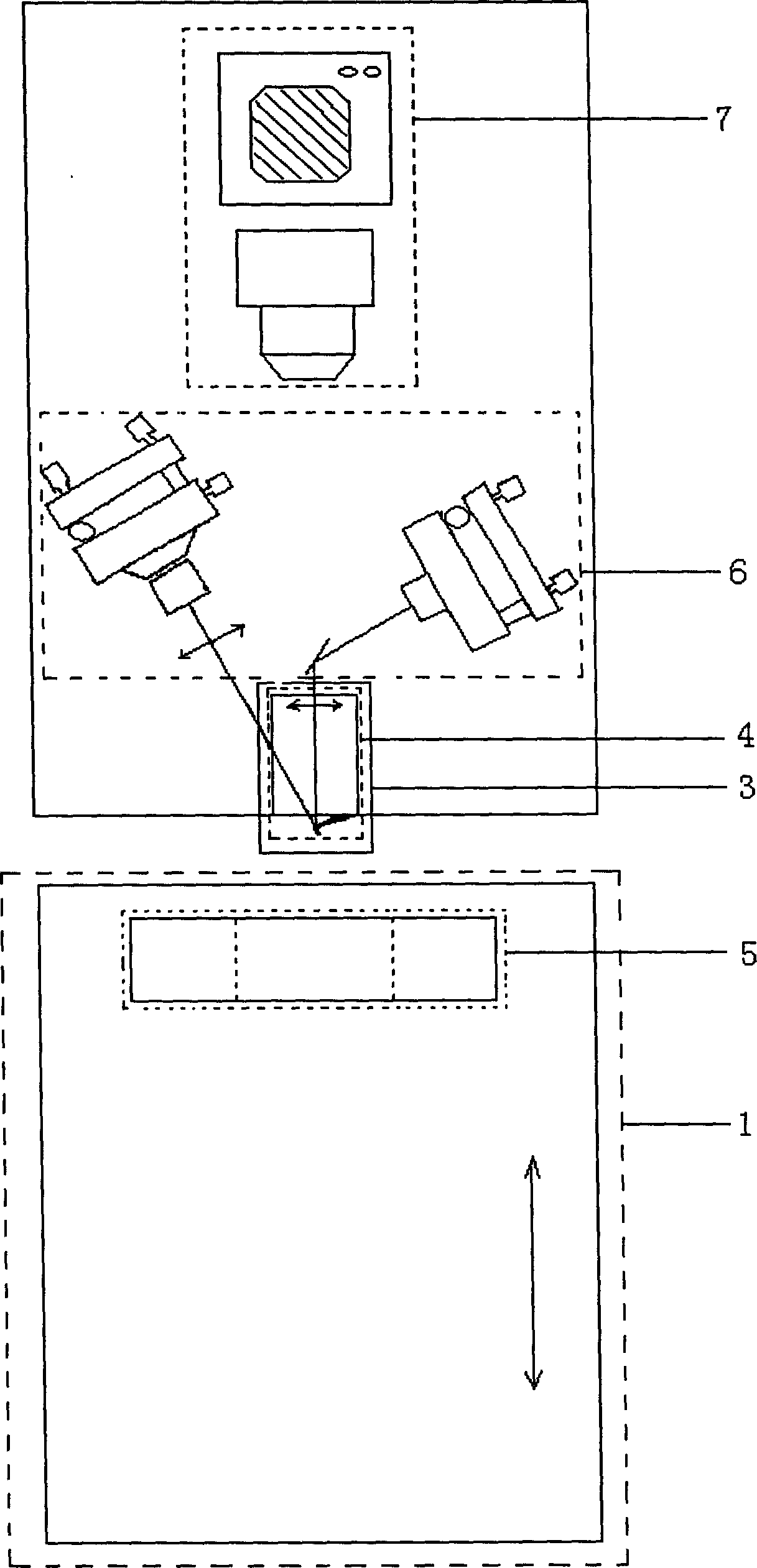
[0029] The principle schematic diagram of embodiment 3 is as Figure 4 As shown, using the above-mentioned modules, just place the sample on the scanner of the fifth module 5, and the first module 1 drives the third module 3, the fourth module 4, and the sixth module 6 to approach the sample from top to bottom , the seventh module 7 is fixed directly above the sample and the needle point with another shelf, and the whole adopts a vertical structure.

[0030] Proved by experiments, the present invention has the following advantages:

[0031] 1. The modular atomic force microscope of the present invention adopts two independent devices separated by xy scanning and z scanning, which can better ensure the orthogonality of scanning motion in the three directions of xyz; the xy direction scanner and the z direction scanner both With a position sensor, the use of a closed-loop feedback loop for the scanner's controller can well ensure a linear relationship between the scanner's inpu...


PUM


Abstract

A modularized atomic energy microscope is disclosed, comprising seven modules. The first one is stepper motor the second is sample support with four-dimensional adjustment fixed on stepper motor, the third is z direction scanner, the fourth consists of microbracket needle point and focusing lens, the fifth is xy direction scanner, the sixth consists of semiconductor laser with focusing lens, reflector, imaging lens and four-quadrant photoelectric sensor, the seventh consists of optical microscope, CCD camera, monitor. The invention has convenient adjustment and replacement to modularized atomic energy microscope, and using each module to construct atomic energy microscope with different structure is easy and sample has function of coarse positioning.

Description

technical field [0001] The invention relates to an atomic force microscope, in particular to a modular atomic force microscope. Background technique [0002] Atomic force microscope is a surface measurement instrument with extremely high resolution, which is an important basis for the development of nanotechnology. It can not only observe the atomic topography of conductors and semiconductor surfaces from the atomic scale like a scanning tunneling microscope, but also obtain the microstructure of non-conductor surfaces such as glass, ceramics, and biological samples; Damaged samples were directly observed. Therefore, the atomic force microscope has a wide range of applications. Most existing atomic force microscopes use piezoelectric ceramic tubes as scanners, which have a fixed structure and are therefore only suitable for certain applications. For example, some are only suitable for small sample detection, while others are only suitable for large and large area sample d...

Claims


Application Information

Patent Timeline
Patent Type & Authority Patents(China)
IPC IPC(8): G01N13/16G01Q60/24
CPCG01Q10/02G01Q10/04G01Q20/02G01Q30/025
Inventor 徐文东杨金涛吉小明
Owner SHANGHAI INST OF OPTICS & FINE MECHANICS CHINESE ACAD OF SCI
Learn More