Layer and chamber integrated clean combustion arrangement

A technology of clean combustion and chamber combustion, applied in the field of combustion devices, can solve the problems of complex structure of gas generator and combustion chamber, inconvenient for use of horizontal boilers, poor processing technology, etc., achieving compact structure, convenient maintenance and repair, The effect of improving the thermal efficiency of combustion

Inactive Publication Date: 2006-10-18
冯栓海
View PDF1 Cites 0 Cited by
  • Summary
  • Abstract
  • Description
  • Claims
  • Application Information

AI Technical Summary

Problems solved by technology

However, there are still many unsatisfactory aspects of this kind of boiler after actual use: First, because the gas generator is set in the center of the combustion chamber cavity, it is more suitable for use on vertical boilers, and it is not convenient to use it on horizontal boilers, etc. Adoption, limits the application of interlayer and chamber combustion integrated clean combustion technology in boilers and other fields; secondly, the gas generator is welded into a water jacket structure from the inner and outer cylinders, and the air guide hole and the smoke exhaust port must be welded on the interlayer wall of the water jacket. etc., which make the structure of the gas generator and the combustion chamber complex, the processing technology is not good, and it is not easy to maintain and repair

Method used


Image

  • Layer and chamber integrated clean combustion arrangement
  • Layer and chamber integrated clean combustion arrangement

Examples


Embodiment Construction

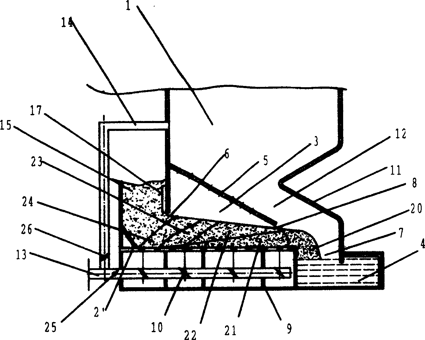
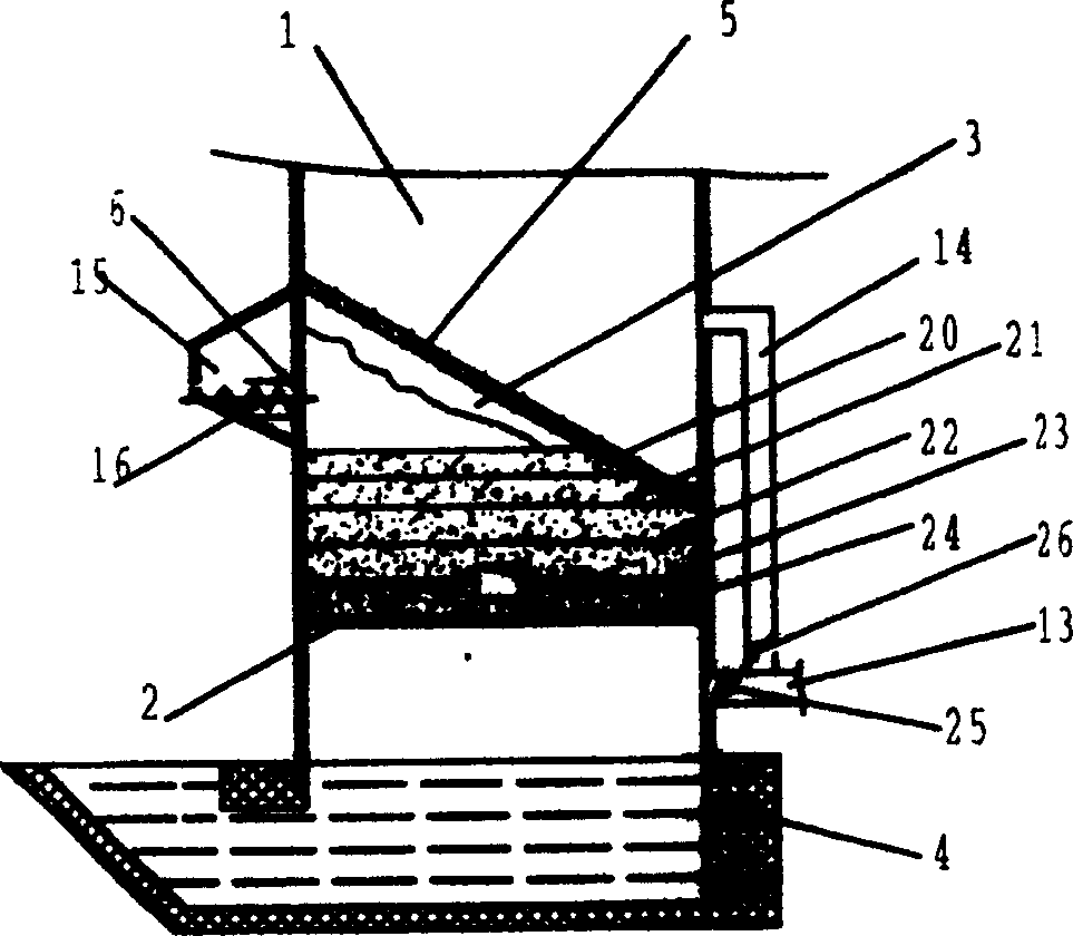
[0020] The parts in the attached drawings are labeled: 1 combustion chamber, 2 fixed grate, 2'movable grate, 3 gas generator, 4 water-sealed tank, 5 air guide hole, 6 coal inlet, 7 slag outlet, 8 coal outlet , 9 dividing plate, 10 adjusting air door, 11 rear arch, 12 oblique passage, 13 primary air inlet pipe, 14 secondary air inlet pipe, 15 coal scuttle, 16 coal feeder, 17 ram, 20 slag layer , 21 oxidation layer, 22 reduction layer, 23 dry distillation layer, 24 dry layer, 25 primary air control damper, 26 secondary air control damper.

[0021] Attached figure 1 It is the basic structure used in vertical boilers. When the vertical boiler with this structure is used, the burnt-out slag falls into the water-sealed pool 4 to produce water vapor. After a large amount of primary air and water vapor are mixed, it passes through the slag layer 20 and enters the oxide layer 21, where a violent oxidation reaction occurs and releases When a large amount of heat and a large amount of carbo...


PUM


Abstract

An integrated clean combustion device with layer and chamber combustion, which relates to a combustion device using coal as fuel, belongs to the technical field of combustion devices, and is used to solve the defects of narrow adaptability and poor processability of existing such devices. There are combustion chamber, grate, gas generator, water seal pool, and primary and secondary air ducts. After improvement, the gas generator is obliquely offset on the bottom side of the combustion chamber, and the air guide holes on it are arranged along the inclined top wall. . After adopting the inclined offset structure, the raw coal can be piled up above the fixed grate by intermittent addition, and can also enter from the offset side with the advancement of the movable grate, so that the present invention can be adapted to both vertical boilers and horizontal boilers. type boiler and other coal-fired devices, which expands the application range of the layer chamber combustion technology, and simplifies the structure of the gas generator and even the combustion chamber, and has the advantages of good processing technology, compact structure, and convenient maintenance and repair. It is suitable for various Various vertical and horizontal boilers, industrial coal-fired furnaces and civilian stoves.

Description

Technical field [0001] The invention relates to a combustion device using coal as fuel, and belongs to the technical field of combustion devices. Background technique [0002] Combustion devices that use coal or pulverized coal as fuel are classified according to the combustion method, which can be divided into layer-by-layer combustion of raw coal, room-combustion method in which coal gas or pulverized coal is ignited and burned in the combustion chamber, and coal under forced blast. Boiling combustion method. These types of combustion methods have their own characteristics: stratified combustion technology is mostly used in vertical fixed grate boilers. Raw coal is manually intermittently added to the fixed grate. Combustion-supporting air passes through the coal seam under the grate into the furnace, and the coal is burned sequentially from top to bottom. Go through four stages or stages: drying, dry distillation, volatile matter ignition and burning, and coke burnout. Its adv...

Claims


Application Information

Patent Timeline
Patent Type & Authority Patents(China)
IPC IPC(8): F23B10/00F23B10/02
Inventor 冯栓海冯慧琴李静海白健康陈建忠
Owner 冯栓海
Why Eureka
Try Eureka