

Connector terminal, connector and manufacturing method thereof
A technology of a connector terminal and a manufacturing method, which is applied in the field of connectors in China, can solve problems such as poor bonding, and achieve the effects of preventing the reduction of workability, less burden, and suitable hardness.
- Summary
- Abstract
- Description
- Claims
- Application Information
AI Technical Summary
Problems solved by technology
Method used
Image

Examples
Embodiment 1
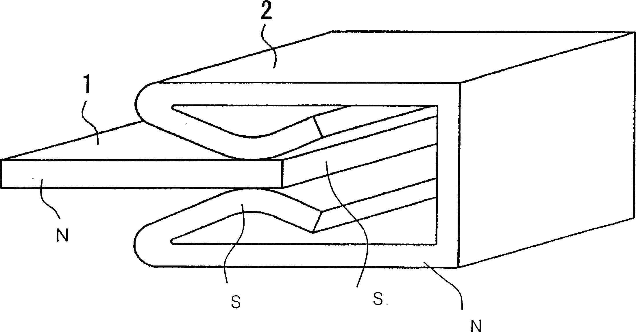
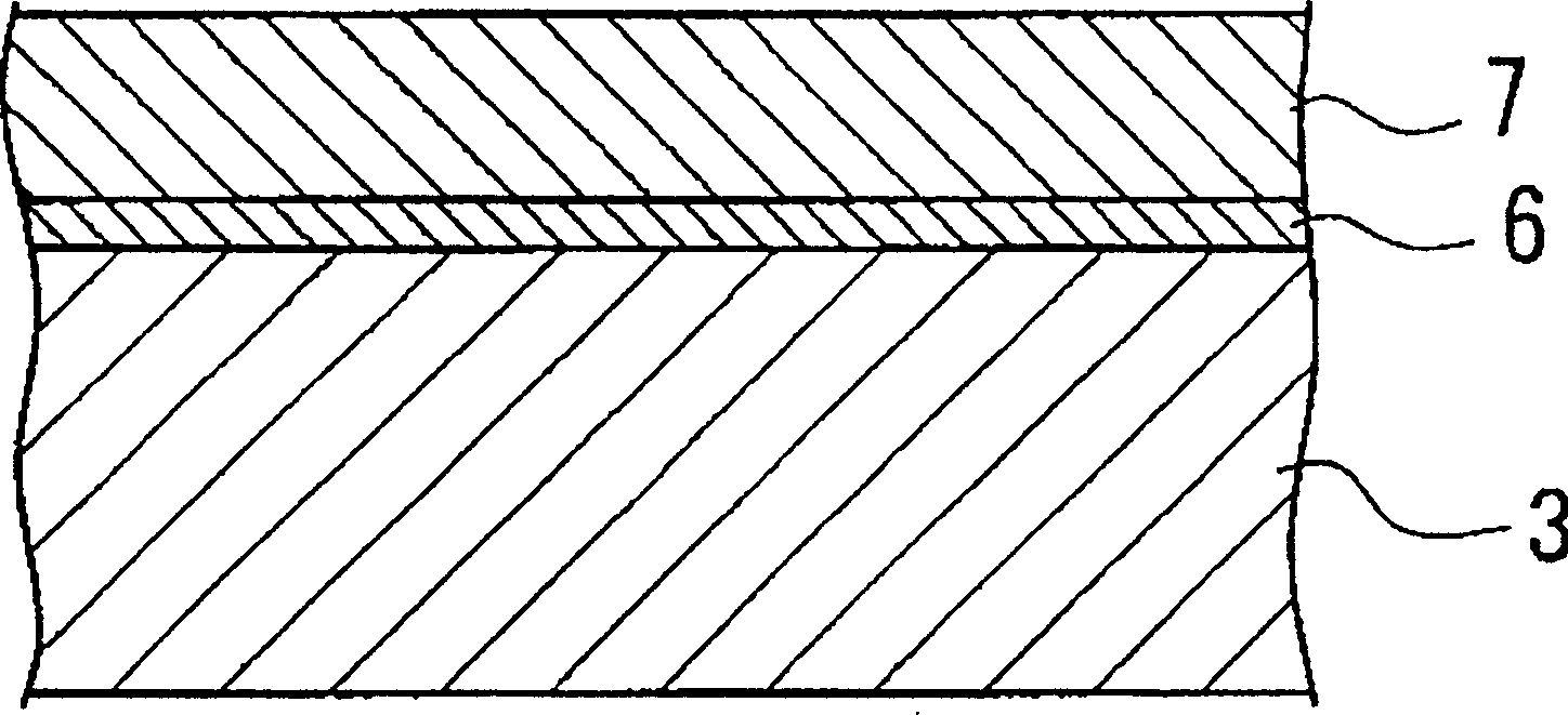
[0130] As the plating strips J constituting the connector terminals 1 and 2 described above, commercially available copper alloy strips A and B (refer to Table 1) that have undergone resolvation and Sn plating were subjected to high frequency in the atmosphere under various conditions while passing through a furnace. One end portion thereof was heated to obtain a copper alloy strip having both a surface-cured region in which the alloy layer was sufficiently formed and the surface was solidified, and other regions in which the surface was hardly solidified. The average thickness of the alloy layer and the remaining Sn layer, the measurement of hardness (HV) (with a load of 10 g), the evaluation of 90 ° W bendability, and the evaluation of solderability were performed on the surface solidified regions of these copper alloy strips.
[0131] 【Table 1】
[0132] The thicknesses of the plated alloy layer and the remaining Sn layer were mainly obtained by electrolytic film thickness g...
Embodiment 2
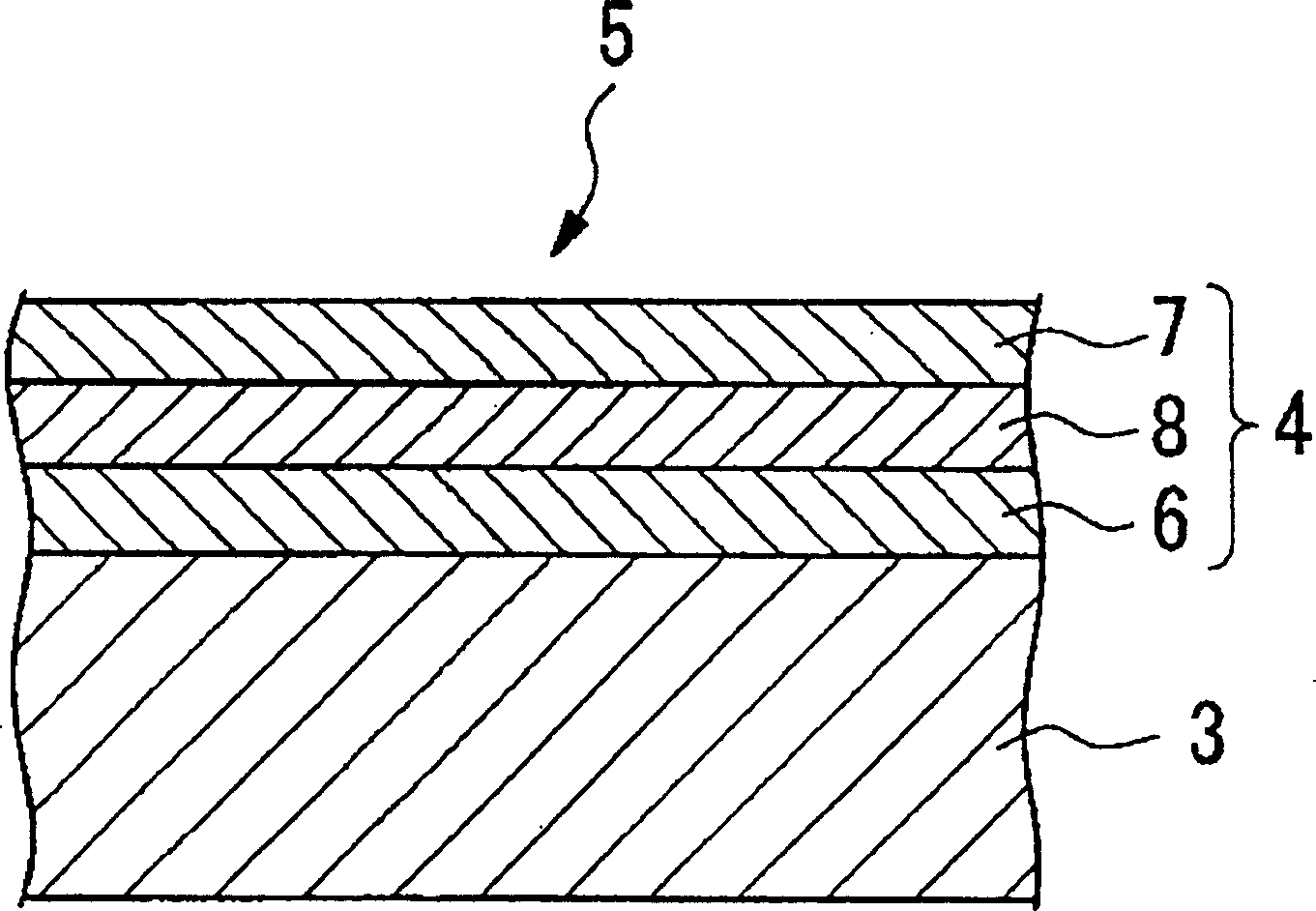
[0139] A commercially available copper alloy strip C (see Table 1) was plated with Ni or Sn / Ni alloy plating (Ni: about 26%) on one end of about 10 mm in width, and Sn plated the remaining portion.
[0140] For each plated portion of these copper alloy strips, the measurement of the thickness and hardness of the plated layer, the evaluation of 90° W bendability, and the evaluation of solderability were performed. Various methods of evaluating and
[0141] Example 1 is the same.
[0142] Each plating condition is as follows.
[0143] [Ni plating]
[0144] Plating bath composition: nickel sulfate 240g / L, nickel chloride 45g / L, boric acid 30g / L, plating bath temperature: 35°C, current density: 2A / dm 2
[0145] [Sn / Ni alloy plating]
[0146] Plating bath composition: pyro alloy SN starter 500mL / L, tin pyrophosphate 25g / L, plating bath temperature: 40°C, current density: 1A / dm 2
[0147] [Sn plating]
[0148] Plating bath composition: stannous sulfate 60g / L, sulfuric acid 5...
Embodiment 3
[0153]The area including the sliding part of the commercially available refractory Sn-plated copper alloy terminal is subjected to the following three kinds of local annealing and curing treatments in the atmosphere, that is, AC local heating treatment, high-frequency heating treatment, and laser heating treatment. The thickness of the alloy layer and the remaining Sn layer and the hardness were measured for these hardened portions, and the insertion force of the male terminal and the female terminal was evaluated.
[0154] The composition, hardness, etc. of each terminal material (D-I) are shown in Table 1. The number of samples of N=5 was evaluated under various conditions, and the results are shown in Tables 4-6.
[0155] 【Table 4】
[0156] Table 4 is an example of AC localized heating of the area of the 090 type terminal including the sliding portion of the male terminal having a width of 0.090 inches (approximately 2.29 mm).
[0157] In No. 1, when neither the male te...
PUM
| Property | Measurement | Unit |
|---|---|---|
| Hardness | aaaaa | aaaaa |
| Vickers hardness | aaaaa | aaaaa |
| Vickers hardness | aaaaa | aaaaa |
Abstract
Description
Claims
Application Information