Blast furnace slag flushing technology by pneumatic lifting runner and its flushing device

A blast furnace slag and hub technology, which is applied in the field of blast furnace slag punching process and its punching device by the air-lifting hub method, can solve the problems of high frequency of dry slag, high slag content in circulating water, and low equipment operation rate, etc. problems, to achieve the effects of long equipment life, water and energy saving in slag water content, and low operating costs

Inactive Publication Date: 2007-04-25
天津市隆安冶金机械厂
View PDF4 Cites 0 Cited by
  • Summary
  • Abstract
  • Description
  • Claims
  • Application Information

AI Technical Summary

Problems solved by technology

The INBA method has the disadvantages of complex process and expensive investment. Generally, small and medium-sized blast furnaces require a high proportion of investment and occupy too much land.
Because the Tula method (or wheel method) uses a granulation wheel, it increases the failure of the system, makes the equipment operation rate very low, and the number of dry slag is more
In addition, the INBA method and the Tula method still have the problem of large slag content in the circulating water, which has been plagued by many manufacturers.

Method used


Image

  • Blast furnace slag flushing technology by pneumatic lifting runner and its flushing device
  • Blast furnace slag flushing technology by pneumatic lifting runner and its flushing device
  • Blast furnace slag flushing technology by pneumatic lifting runner and its flushing device

Examples


Embodiment Construction

[0027] Below in conjunction with accompanying drawing and concrete example for further description:

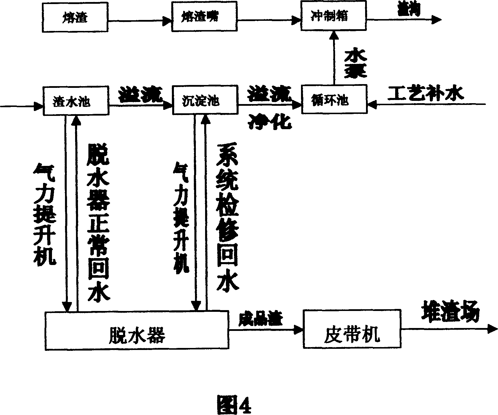
[0028] As shown in Figure 4, the blast furnace slag punching process of the present invention includes the following steps in turn:

[0029] A. The slag separated by the skimmer flows to the slag nozzle through the slag ditch;

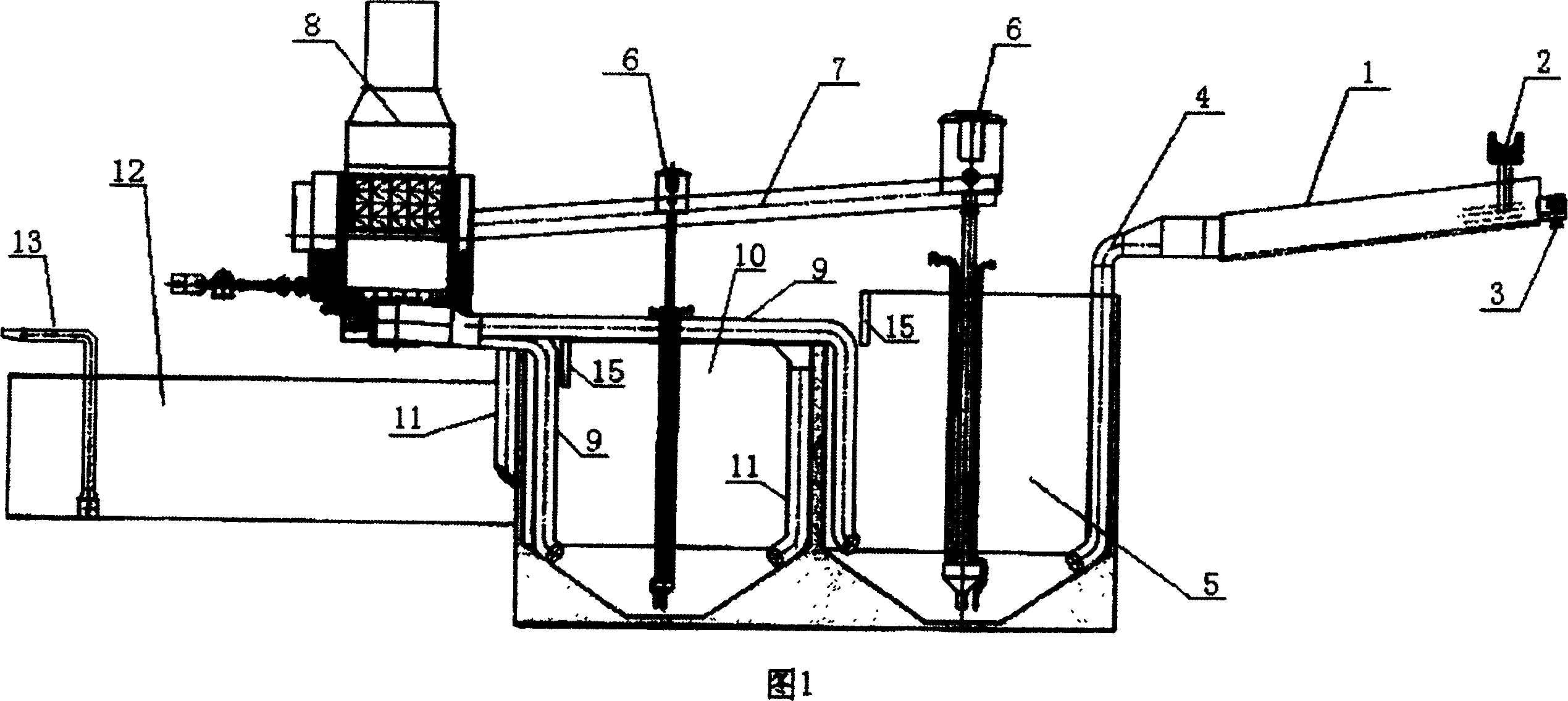
[0030] B. The slag discharged from the slag nozzle is mixed with the water sprayed from the punching box, and then discharged into the bottom of the slag pool through the slag flushing ditch and the water diversion pipe;

[0031] C. The pneumatic lift pump transports the slag water at the bottom of the slag pool to the hub type dehydrator for dehydration. The dehydrated slag is sent to the slag dump by the belt conveyor. The bottom of the slag water tank is transported to the bottom of the sedimentation tank through the return pipe during system maintenance; the overflow water from the slag water tank is led to the bottom of the sedimentation tank;

...


PUM


Abstract

A pneumatic lifting-hub rotating technology and system for flushing the slags of blast furnace includes such steps as skimming the molten slags in slag ditch, flowing to slag tap, flushing it by the water, flowing the mixture of slags and water in slag-water pool via slag flushing ditch and water pipe, pneumatically lifting the slag in hub-rotating dewatering machine, dewatering, discharging the dewatered slags, delivering the water into slag-water pool or depositing pool, pneumatically lifting the slag deposit in hub-rotating dewatering machine for dewatering, and reusing the overflowed water of depositing pool.

Description

technical field [0001] The invention relates to a treatment method for blast furnace slag, in particular to a blast furnace slag punching process and a punching device by the air-lifting hub method. Background technique [0002] Blast furnace slag is a by-product formed by the reaction and melting of gangue and coke ash in the ore added to the furnace and flux. It is a complex silicate containing various oxides, often containing a small amount of sulfide, fluoride, etc. Its composition and yield vary depending on the composition of the blast furnace feedstock and fuel. The amount of slag generated per ton of iron smelting (ie the ratio of slag to iron) is roughly 300-600 kg. The main components of blast furnace slag are: CaO35~40%, SiO 2 32~42%, Al 2 o 3 6-16%, also contains a small amount of MgO, FeO and S, etc. The specific gravity of blast furnace slag: 2.2-2.5 in liquid state, 2.3-2.7 in solid state; the temperature of slag released from the furnace is 1400-155°C, a...

Claims


Application Information

Patent Timeline
Patent Type & Authority Patents(China)
IPC IPC(8): C21B3/06
CPCY02P10/20Y02W30/50
Inventor 安振波
Owner 天津市隆安冶金机械厂
Why Eureka
Try Eureka