Eureka AIR delivers breakthrough ideas for toughest innovation challenges, trusted by R&D personnel around the world.

Method and device for making prefabricated optical fibre

A technology for optical fiber preforms and manufacturing methods, which is applied in the direction of manufacturing tools, optical components, and glass manufacturing equipment, and can solve problems such as uneven growth of optical fiber preforms, unstable deposition processes, and large fluctuations in the core-to-core ratio. Surface cracking, elimination of air flow turbulence, and uniform outer diameter

Inactive Publication Date: 2007-05-30
ZHEJIANG FUTONG OPTICAL FIBER TECH
View PDF7 Cites 0 Cited by
  • Summary
  • Abstract
  • Description
  • Claims
  • Application Information

AI Technical Summary

Problems solved by technology

The degassing effect of this manufacturing method and device is poor, making it impossible to deposit formed SiO 2 (Silicon dioxide), GeO 2 (germanium dioxide) particles are more trapped in the reaction vessel, resulting in the following defects:
[0004] 2. As the deposition length of the optical fiber preform increases, the remaining SiO not deposited on the preform 2 、GeO 2 Particles are continuously deposited on the wall of the reaction vessel with lower temperature (especially on the upper side of the exhaust port) to form a mirror surface, which reflects heat, causing the temperature in the reaction vessel to rise gradually, which eventually leads to an unstable deposition process and fluctuations in the deposition rate
[0005] 3. Remaining SiO not deposited onto the preform 2 、GeO 2 Particles will also adhere to the preform that has been deposited and formed, which causes the inhomogeneous growth of the optical fiber preform along the axial direction, such as the core-to-core ratio everywhere along the axial direction (that is, the cylindrical outer shell with different optical refractive indices). The ratio of layer to inner layer diameter) fluctuates greatly
[0006] 4. Due to the SiO deposited on the inner wall of the reaction vessel 2 、GeO 2 The particles are peeled off and attached to the surface of the optical fiber preform being deposited to form a less dense area. When the optical fiber preform is vitrified in the subsequent process, bubbles will be generated in this area, which will cause the optical fiber preform to be pulled Fiber breakage occurs during the process of making optical fibers

Method used


Image

  • Method and device for making prefabricated optical fibre
  • Method and device for making prefabricated optical fibre

Examples


Embodiment 1

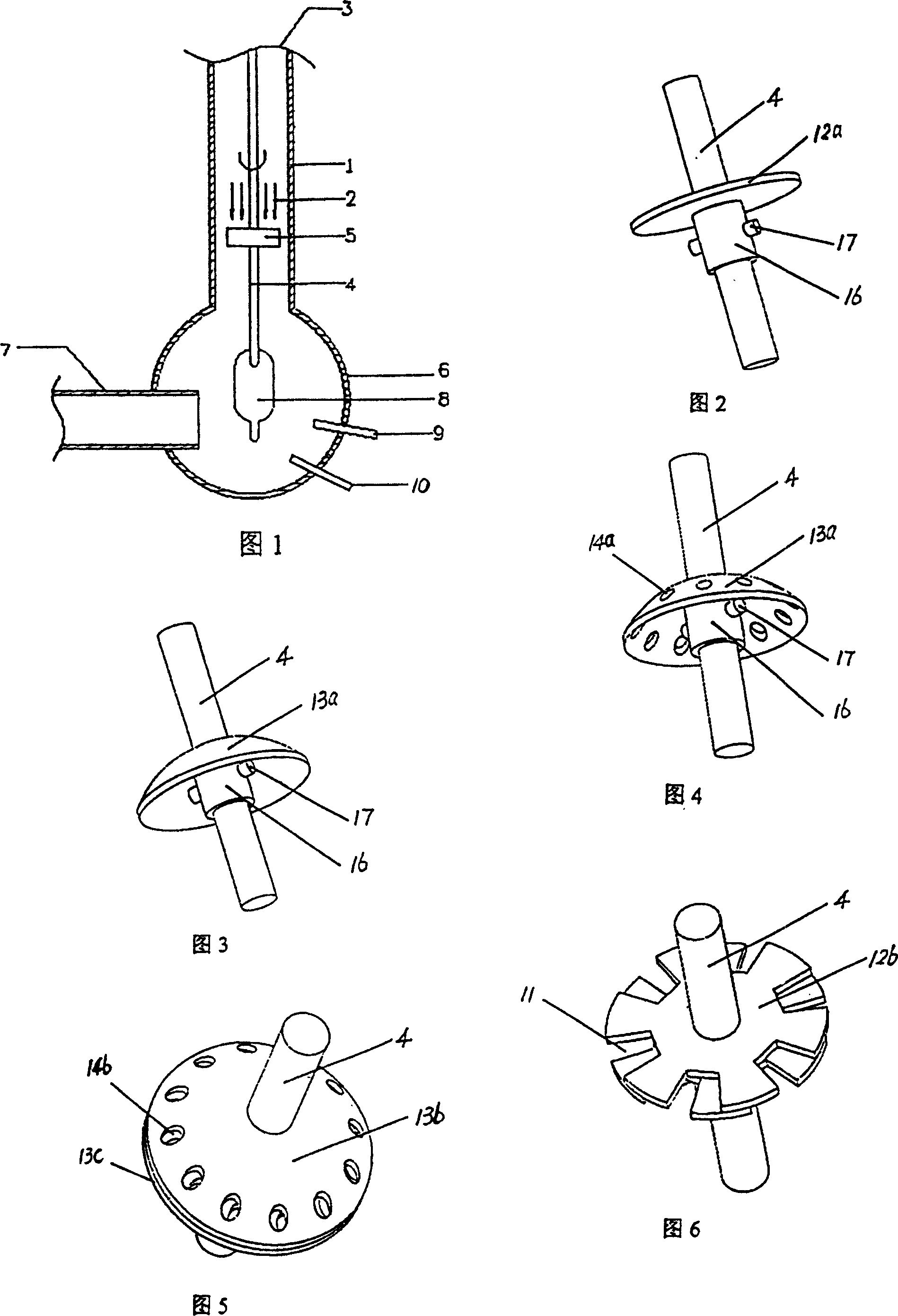
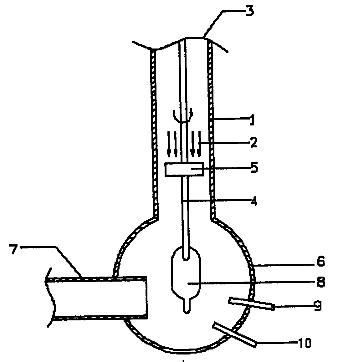
[0033] Embodiment 1: In the case of exhausting air from the exhaust port 7, first install the airflow regulator 5 with a diameter of 145mm on the seed rod 4 with a diameter of 25mm through the sliding sleeve 16 and the set screw 17, and then install the seed rod 4 Insert the air inlet 3 at the upper end of the flange pipe 1 with an internal diameter of 250mm into the spherical reaction vessel 6, and make the lower end of the seed rod 4 correspond to the two spray guns, rotate the seed rod at a uniform speed, and the exhaust port is connected with the exhaust fan. The pressure is controlled at about 100Pa, and the exhaust is started; the air inlet at the upper end of the flange tube is introduced into the reaction vessel with a pressure of about 0.5×10 5 Pa, air rectification air flow 2 with a temperature of about 20°C; then feed hydrogen and oxygen into the two spray guns, and ignite a hydrogen-oxygen flame at about 1000°C in the reaction vessel, and then feed the first spray g...

Embodiment 2

[0034] Embodiment 2: The difference from Embodiment 1 is that the pressure is about 2.0×10 from the air inlet on the upper end of the flange pipe into the reaction vessel. 5 Pa is heated to 600 ° C nitrogen rectification airflow 2; make the reaction in a balanced state for a certain period of time, you can get the predetermined requirements of the optical fiber preform; because the rectification airflow is selected from heated nitrogen with stable properties, it can be more Keep the temperature in the reaction vessel stable, and the reaction effect is better.

[0035] In the case of using an inert gas for the rectified gas flow, it is mainly because the stability of the inert gas is good, which can better ensure the stability of the reaction process.

[0036] For the three gases used to rectify the airflow, their temperature and pressure can be selected according to actual needs.

[0037] It should be noted that during the manufacturing process, the rectified airflow is limit...


PUM


Abstract

The present invention relates to a production method of optical fibre prefabricated member and its equipment. It is characterized by that the upper portion of the ball reaction container whose side surface is equipped with exhaust opening and lower portion is equipped with spray gun is connected with flange tube in which an air flow regulating component is set. The seed rod is placed in the reaction container through flange tube and is directed at spray gun, and then the commutating air flow whose pressure is 0.5X10 to the power 5-2.0X10 to the power 5 Pa and temp. is 20-600 deg.C is downward introduced from upper end of flange tube, and can be passed through the air flow regulating component and flowed along the inner wall of the flange tube and reaction container, then discharged from exhaust opening so as to eliminate inordinance of air flow.

Description

【Technical field】 [0001] The invention relates to a method and device for manufacturing an optical fiber preform, belonging to the field of optical fiber manufacturing. 【Background technique】 [0002] Inorganic optical fibers have been widely used in the communication industry, among which quartz-based optical fibers have become the leading inorganic optical fibers due to their advantages such as low optical loss, wide range of applicable light waves, and adaptability to long-distance communication. Among the methods for manufacturing quartz-based optical fiber preforms, there is a vapor phase axial deposition method (VAD method). The manufacturing device used in it includes a reaction vessel with an exhaust port. A spray gun is used to vertically set seed rods in the reaction vessel. When manufacturing optical fiber preforms, place the seed rod vertically in the reaction vessel corresponding to the spray gun, pass hydrogen and oxygen into the spray gun and ignite in the re...

Claims


Application Information

Patent Timeline
Patent Type & Authority Patents(China)
IPC IPC(8): C03B37/012C03B37/018G02B6/00
CPCC03B37/01406C03B37/01486
Inventor 儿玉喜直森昭彦山本岳彦徐衠曹松峰
Owner ZHEJIANG FUTONG OPTICAL FIBER TECH
Why Eureka
Eureka Blog
Learn More