Manufacture of prefabricated fiber rod

An optical fiber preform and a manufacturing method technology, which is applied to manufacturing tools, glass manufacturing equipment and other directions, can solve the problems of long equipment occupation time, low production efficiency, increased cost of sleeves, etc., so as to achieve short equipment occupation time, improve production efficiency, High deposition efficiency

Inactive Publication Date: 2002-02-27
YANGTZE OPTICAL FIBRE & CABLE CO LTD
View PDF0 Cites 16 Cited by
  • Summary
  • Abstract
  • Description
  • Claims
  • Application Information

AI Technical Summary

Problems solved by technology

Although the MCVD+OVD manufacturing method solves some defects in the above-mentioned manufacturing method, such as the eccentricity and curvature of the casing and the concentricity of the two after the mandrel is inserted; Large bushings raise cost concerns
However, this method has a low raw material utilization rate when depositing a glass film in the liner, and the control of the refractive index of the optical fiber is not precise enough, and the deposition and melting are carried out on the same equipment, which takes a long time for the equipment and has the disadvantages of low production efficiency.

Method used


Image

  • Manufacture of prefabricated fiber rod
  • Manufacture of prefabricated fiber rod
  • Manufacture of prefabricated fiber rod

Examples


Embodiment Construction

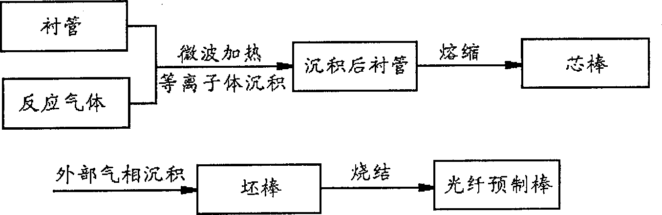
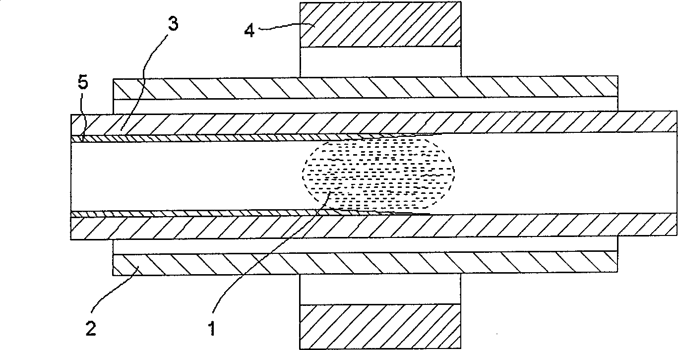
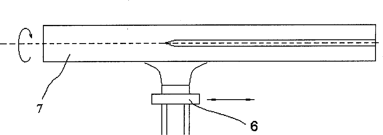
[0018] The manufacturing method of the present invention will be further described below in conjunction with the accompanying drawings.

[0019] Such as Figure 1 to Figure 6 As shown, the present invention firstly passes the parent material into a rotating quartz glass liner 3, and the resonant cavity 4 couples microwaves to the reaction gas in the liner 3 to excite it into plasma 1, which is deposited in the liner 3 A glassy deposition layer 5 is formed on the surface. When sufficient layers of glass-breaking film are deposited in the liner 3, the liner is heated in a heat source 6 to melt and shrink it into a solid preform, which is the mandrel 7. Then, the reaction raw material is sent to the burner 8 through the conveying system by the vapor phase deposition method outside the tube, and the flame hydrolysis is carried out with the oxyhydrogen flame 9 containing the reaction raw material, and SiO2 dust 11 is deposited on the mandrel. Hang the billet vertically on the grab...


PUM


Abstract

The production method of optical fibre preform includes the following steps: A. adopting plasma chemical vapor phase deposition method to prepare core rod; B. adopting outside vapor phase deposition method to prepare cladding, i,e, obtaining blank rod; and C. sintering blank rod to obtain the optical fibre preform. It can accurately control optical fibre waveguide structure, and possesses the advantages of high raw material utilization rate, short production period and high production efficiency.

Description

technical field [0001] The invention relates to a method for manufacturing an optical fiber preform, in particular to a method for manufacturing an optical fiber preform by combining two processes of plasma chemical gas deposition and external vapor deposition. Background technique [0002] There are mainly four traditional manufacturing methods for optical fiber preforms, namely plasma chemical vapor deposition, improved chemical vapor deposition, out-of-tube vapor deposition and axial vapor deposition. Although these four manufacturing processes can produce optical fiber preforms, they each have different disadvantages. In recent years, with the development of optical fiber preform manufacturing technology, the four manufacturing processes have begun to merge, and some hybrid manufacturing methods have emerged, such as improved chemical vapor deposition and out-of-tube vapor deposition hybrid manufacturing methods (MCVD+OVD manufacturing methods). ...

Claims


Application Information

Patent Timeline
Patent Type & Authority Applications(China)
IPC IPC(8): C03B37/018
Inventor 谢康拉吉·马泰程铭张穆
Owner YANGTZE OPTICAL FIBRE & CABLE CO LTD
Why Eureka
Try Eureka