

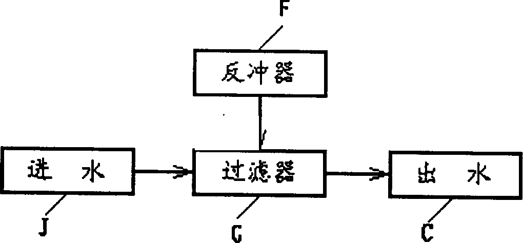
Clarification system through continuous microstraining intermdeiate water
A purification system and microfiltration technology, applied in filtration and separation, chemical instruments and methods, fixed filter element filters, etc., can solve the problems of difficult backwashing, limited use, easy clogging, etc. long life effect
- Summary
- Abstract
- Description
- Claims
- Application Information
AI Technical Summary
Problems solved by technology
Method used
Image

Examples
Embodiment Construction
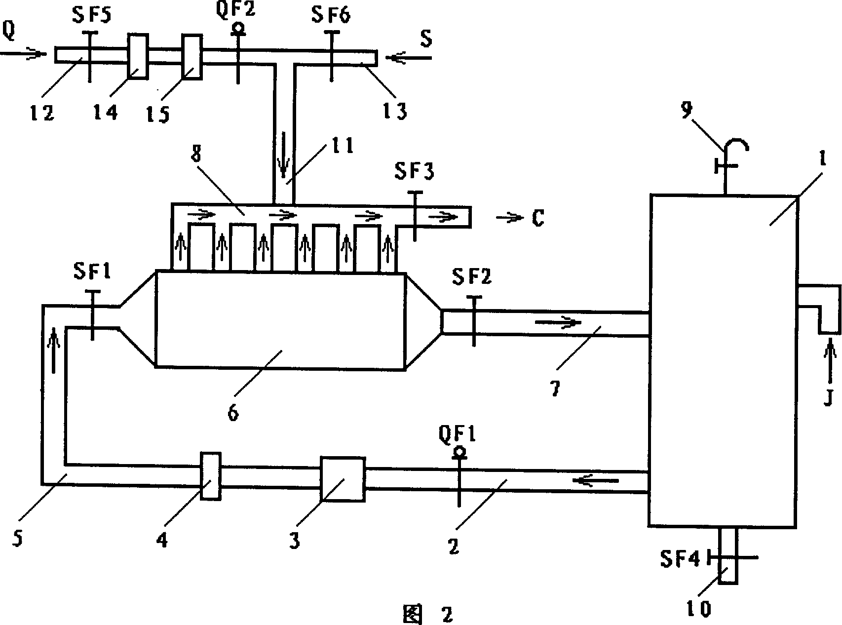
[0021] The composition of the present invention can be seen from Fig. 2:
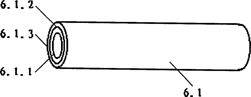
[0022] ①Filter G is composed of the following components and connected in the following order: intermediate tank 1→main pipeline 2→pneumatic butterfly valve QF1→booster pump 3→high and low pressure protection switch 4→confluence pipe 5→manual butterfly valve SF1→membrane module 6→ Manual butterfly valve SF2→reflux pipe 7→tundish tank 1; membrane module 6→permeate pipeline 8→manual butterfly valve SF3; tundish 1 has vent hole 9 on the top, drain pipe 10 on the bottom, and manual butterfly valve SF4 on the drain pipe;
[0023] ②The recoiler F is composed of the following components, and its connection relationship is: the head end of the recoil pipe 12 is connected with the gas pipe 12 and the water pipe 13 respectively; the tail end is connected with the permeate pipe 8; Manual butterfly valve QF5, two-position three-way valve 14, cylinder 15, pneumatic butterfly valve QF2; manual butterfly valve QF6 is ...
PUM
 Abstract
Description
Claims
Application Information