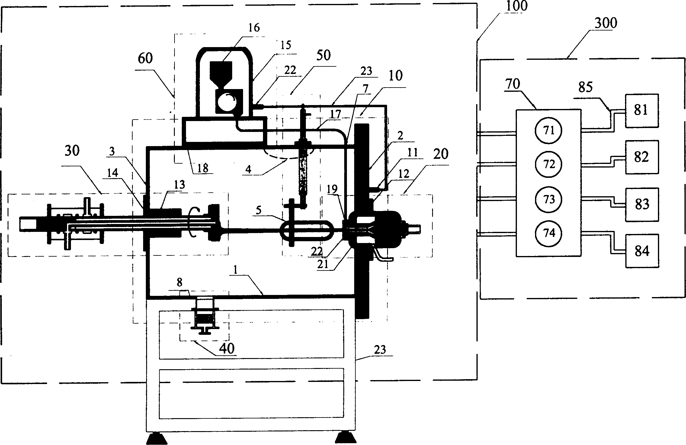
Laminar flow plasma spraying equipment and method
A technology of plasma and spraying equipment, which is applied in the direction of liquid spraying equipment, spraying equipment, liquid spraying equipment, etc., to achieve the effects of increasing the preheating temperature range, controlling oxidation, and improving interface bonding force
- Summary
- Abstract
- Description
- Claims
- Application Information
AI Technical Summary
Problems solved by technology
Method used
Image
Examples
Embodiment 1
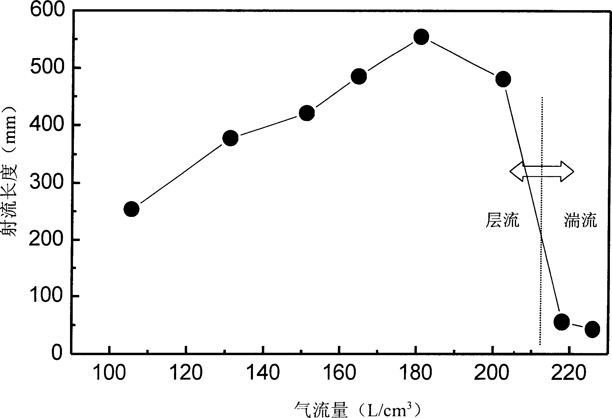
[0035] Embodiment 1: Laminar decompression plasma jet is used to prepare zirconia ceramic or aluminum oxide coating on the surface of stainless steel substrate. Table 1 Experimental parameters Spraying, powder feeding gas Ar powder feeding gas flow rate (cm 3 / s) 8 total air flow (cm 3 / s) 180 Vacuum chamber air pressure (Pa) 1.3×10 4 Input power (kW) <8 Deposition distance (mm) 200~220 Substrate initial temperature (K) 600~900
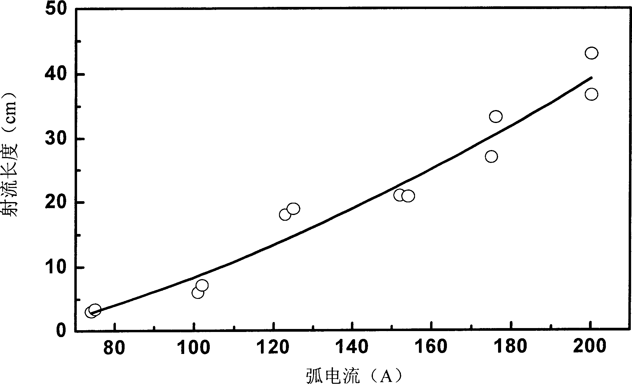
[0036] In the embodiment of the present invention, the substrate is 1Cr18Ni9Ti stainless steel. Powder is ZrO 2 -8mol%Y 2 o 3 Ceramic powder, the particle size of which is less than 25 μm. The diameter of the anode outlet is 20mm. The laminar jet reaches a length of 600mm and a diameter of about 25mm. The relevant spraying experimental parameters are listed in Table 1.
[0037] After generating a stable laminar plasma jet, turn on the powder feeding gas valve and the power switch of the powder feeder for powder feeding to realize laminar plas...
Embodiment 2
[0038] Embodiment 2. Atmospheric pressure laminar flow plasma jet is used to prepare a metal or ceramic coating on the material surface. The workpiece can be installed on the tool holder and workpiece holder of the lathe, and the transmission device of the lathe is used as the workpiece transmission frame. The generator outlet diameter is 6mm. When the output power of the power supply is 9kW, the total air flow is 200cm 3 / s under the condition of argon plasma jet flow, the flow rate of powder supply gas is 6cm 3 / s. The powder is supplied outside the gun. The alumina powder with a particle size of less than 100 μm and the yttria-stabilized zirconia powder with a particle size of less than 25 μm can be fed into the jet high-temperature zone and fully melted.
Embodiment 3
[0039] Embodiment 3, preparation of composite coating material and gradient coating.
[0040] In the embodiment of the present invention, the substrate is 1Cr18Ni9Ti stainless steel. A powder is ZrO 2 -8mol%Y 2 o 3 Ceramic powder, the particle size of which is less than 25 μm. Another powder is NiCrAlY 2 o 3 Powder, the particle size of which is less than 25-75 μm. The diameter of the anode outlet is 20mm. The laminar jet reaches a length of 600mm and a diameter of about 25mm. The relevant spraying experimental parameters are listed in Table 1.
[0041] After generating a stable laminar plasma jet, turn on the powder feeding gas valve and the power switch of the powder feeder for powder feeding to realize laminar plasma spraying. ZrO 2 -8mol%Y 2 o 3 The ceramic powder adopts powder feeding in the gun, NiCrAlY 2 o 3 The powder gun delivers powder outside. When preparing the composite coating, the powder feeding amount of the two powders should be kept constant. ...
PUM
| Property | Measurement | Unit |
|---|---|---|
| angle | aaaaa | aaaaa |
| angle | aaaaa | aaaaa |
| melting point | aaaaa | aaaaa |
Abstract
Description
Claims
Application Information
 - R&D
- Intellectual Property
- Life Sciences
- Materials
- Tech Scout
- Unparalleled Data Quality
- Higher Quality Content
- 60% Fewer Hallucinations
Browse by: Latest US Patents, China's latest patents, Technical Efficacy Thesaurus, Application Domain, Technology Topic, Popular Technical Reports.
© 2025 PatSnap. All rights reserved.Legal|Privacy policy|Modern Slavery Act Transparency Statement|Sitemap|About US| Contact US: help@patsnap.com


