Low density biochip detection method and its system

A biochip and detection method technology, applied in the direction of biochemical equipment and methods, microbial measurement/inspection, etc., can solve problems such as high background, insufficient sensitivity, and limitations of biochips

Inactive Publication Date: 2003-07-23
王红 +2
View PDF0 Cites 8 Cited by
  • Summary
  • Abstract
  • Description
  • Claims
  • Application Information

AI Technical Summary

Problems solved by technology

The CCD method uses photographic technology to image the signal points on the chip at one time and convert them into electrical signals. This method is simple and fast, but has the following disadvantages: (1) the sensitivity is not high enough; (2) the background is high, if you want to reduce the background, You need to use an expensive cooling CCD; (3) There will be in...

Method used


Image

  • Low density biochip detection method and its system
  • Low density biochip detection method and its system
  • Low density biochip detection method and its system

Examples


Embodiment 1

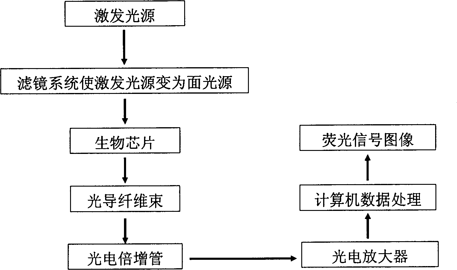
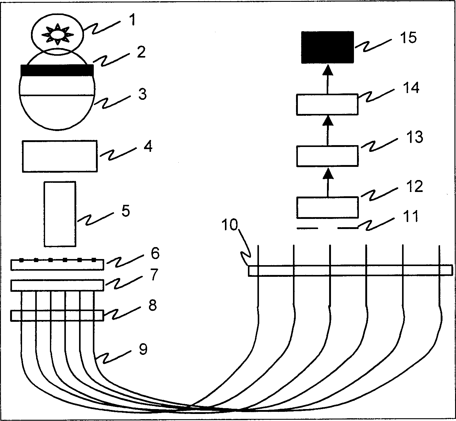
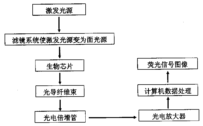
[0022] The mercury arc lamp 1 is used as the laser source, and the infrared rays generated by the heat shield 2 are filtered out, and the excitation light is irradiated to the "mosaic" biochip through the plano-convex lens 3, the plano-convex cylindrical mirror 4 and the plano-convex cylindrical mirror 5 6, wherein 4 and 5 are perpendicular to each other, the purpose is to generate a surface excitation light source that can be irradiated onto the chip surface at the same time. The sample point on the chip 6 generates fluorescence under the excitation of the excitation light, and the fluorescent signal is collected by the optical fiber bundle 9 on the fixing device 8. The optical fiber group 9 forms an angle of 45 degrees with the chip 6, and a planar moving device 10 is used to move the optical fiber group 9 Scatter and fix in a certain sequence, move the planar moving device 10, so that the emitted light from the chip surface points sequentially passes through the pinhole 11 a...

Embodiment 2

[0024] Such as figure 2 As shown, the mercury arc lamp 1 is used as the laser source, and the infrared rays generated by 1 are filtered out by the heat insulation device 2, and the excitation light is irradiated to the "mosaic" ” on the biochip 6, wherein 4 and 5 are perpendicular to each other, the purpose is to generate a surface excitation light source that can be irradiated on the surface of the chip at the same time. The sample points on the chip 6 generate fluorescence under the excitation of the excitation light, and the excitation light is filtered out by the filter 7 , and the optical fiber bundle 9 is in close contact with the filter 7 . Fixing devices 8 are used to fix each optical fiber. In order to transmit the signal in the optical fiber 9 to the photoelectric conversion device 12, a planar moving device 10 is used to disperse the optical fibers 9 and fix them in a certain order, and move the planar moving device 10 so that The emitted light from the surface po...


PUM


Abstract

A system for testing low-density biochip is composed of exciting light unit, fluorescence signal acquiring unit, and signal detecting unit. The said exciting light unit consists of light source, control power supply, infrared filter and lens set. The said fluorescence signal acquiring unit is composed of optical fibre set, optical fibre fixer, isolating filter and planar moving device for opticalfibre set. Said signal detecting unit comprises photoelectric converter, signal amplifier and computer. A process for testing said biochip includes receiving the optical signals from biochip, converting to electric signals, amplifying, and judging the characteristics of points on chip according to amplitude of signal.

Description

technical field [0001] The low-density biochip detection method and system of the present invention relate to a system and method for quickly detecting fluorescent signals in biochips, specifically a method that uses optical fibers to receive optical signals on the chip, and then uses photoelectric amplifiers to convert the optical fibers The transmitted optical signal is converted into an electrical signal, and the nature of the point on the chip is judged according to the magnitude of the electrical signal. Background technique [0002] Biochip integrates thousands or even hundreds of thousands of life information on a small chip through micro-processing technology to achieve the purpose of analyzing and detecting genes, antigens and living cells. Compared with various traditional instruments and biochemical analyzers, it has the advantages of small size, light weight, portability, no pollution, automatic analysis process, fast analysis speed, less samples and reagents req...

Claims


Application Information

Patent Timeline
IPC IPC(8): C12Q1/68
Inventor 王红肖鹏峰刘全俊陆祖宏
Owner 王红
Why Eureka
Try Eureka