
Slide for fluorescent microscope

A fluorescence microscope, glass slide technology, used in microscopes, optics, optical components, etc., can solve problems such as reducing measurement sensitivity and error, and achieve the effect of reducing optical crosstalk, expensive, and high maintenance and operating costs.

Inactive Publication Date: 2003-08-06
CARL ZEISS JENA GMBH
View PDF1 Cites 4 Cited by
  • Summary
  • Abstract
  • Description
  • Claims
  • Application Information

AI Technical Summary

Problems solved by technology

[0006] If a confocal measuring microscope and the described mathematical corrections are not used due to cost, errors are incurred or the measurement sensitivity is reduced

Method used


Image

  • Slide for fluorescent microscope
  • Slide for fluorescent microscope
  • Slide for fluorescent microscope

Examples


Embodiment Construction

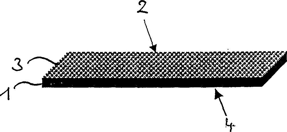
[0037] figure 1 is a perspective view of a glass slide 1 having an upper side 2 on which a fluorescence emitting layer 3 is arranged. For analysis with a microscope, the lower side 4 of the glass slide 1 is placed on a slide holder and the upper side 2 is irradiated with excitation light. The fluorescence light emitted by the excitation is measured in a spatially resolved manner with the microscope objective arranged above the upper side 2 .

[0038] The glass slide 1 is a fluorescent absorbing solid body consisting of a substrate which does not show significant autofluorescence emission in the range between 300 and 700 nm. This substrate is mixed with a fluorescence-absorbing substance, for example a substance based on metal oxides, in such a way that the substrate is completely colored after molding into the flat glass slide 1 . In this case, the complete coloring is such that the absorption requirements are met over the entire cross-section of the glass slide 1 parallel t...


PUM


Abstract

To improve spatial resolution or sensitivity in measuring fluorescent layers, a specimen slide is provided which is not fluorescent by itself, is plate-shaped and has at least one plate side provided with fluorescent light absorbing properties, or with an antireflection-coating for fluorescent radiation.

Description

technical field [0001] The invention relates to a glass slide that does not show autofluorescence, and is especially suitable for fluorescence microscopy or biochip applications. The invention also relates to the use of glass slides in fluorescence microscopy and to a fluorescence microscope with a slide holder on which a glass slide can be placed. Background technique [0002] It is known in fluorescence microscopy and biochip applications that the fluorescence-emitting substances are arranged on a transparent carrier plate, ie a glass slide, for the position-resolved photometric measurement of the fluorescence-emitting substances. The fluorescent substance is then excited by irradiation with suitable light and the fluorescence emission therefrom is then measured in a position-resolved manner. For good accuracy, the error in the fluorescence emission intensity should be kept as small as possible. [0003] Confocal microscopes are therefore currently used for high-precisio...

Claims


Application Information

Patent Timeline
Patent Type & Authority Applications(China)
IPC IPC(8): G02B21/16G02B21/34
CPCG02B21/34G02B21/16
Inventor 彼得·韦斯特法尔托比亚斯·诺伊曼马丁·屈纳迪特尔·格雷费
Owner CARL ZEISS JENA GMBH
Learn More