Liquid cooling LED packaging method

A technology of light-emitting diodes and laser diodes, applied in electrical components, electric solid-state devices, circuits, etc., can solve the problems of high unit price, difficult heat conduction, and high cost

Inactive Publication Date: 2003-09-17
徐继兴
View PDF0 Cites 4 Cited by
  • Summary
  • Abstract
  • Description
  • Claims
  • Application Information

AI Technical Summary

Problems solved by technology

However, due to the high unit price, it has not been widely adopted by consumers
If the luminous efficiency of a single laser light-emitting diode can be improved to achieve higher brightness with less material, or the problem of high cost can be solved, this is a problem to be solved urgently in the present invention
[0009] Generally, the operating current of commonly used light-emitting diodes is limited to about 20mA, and the heat generated is concentrated at 1×10 -3 cm 2 In a small area (about the cross-sectional area of ​​a hair), it is very difficult to effectively conduct this kind of heat, so that the light-emitting diode cannot be operated at a higher power

Method used


Image

  • Liquid cooling LED packaging method
  • Liquid cooling LED packaging method
  • Liquid cooling LED packaging method

Examples


Embodiment 1

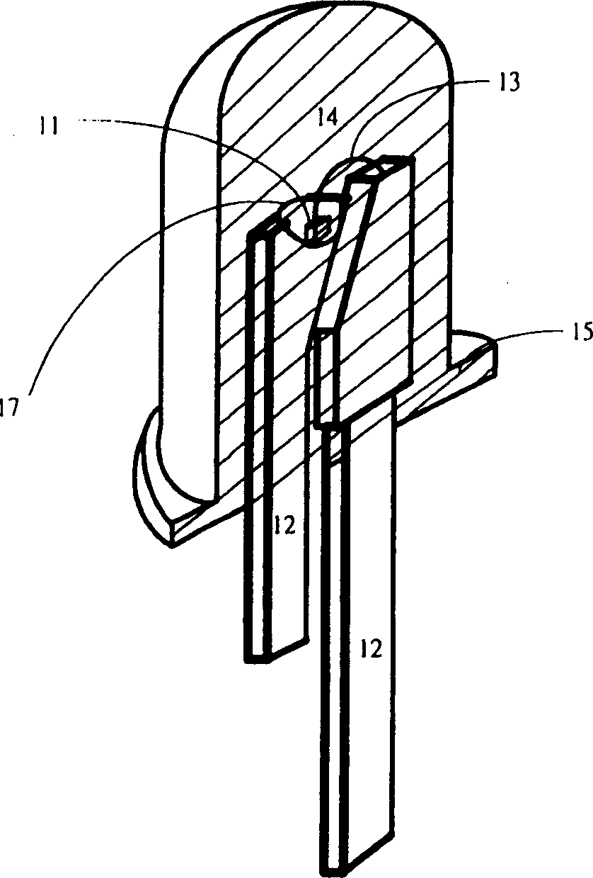
[0107] Embodiment 1 (liquid-cooled light-emitting diode)

[0108] refer to Figure 4 The light-emitting diode crystal grain 11 is fixed on the grain receiving seat 17 at the center of the base 15 with conductive thermal colloid, and then the positive and negative electrode pads on the surface of the crystal grain 11 and the conductive support frame 12 are respectively connected with gold wires or aluminum wires 13 The top of the LED, so that the light-emitting diode crystal grain 11 can be connected to the external circuit (not shown) through the conductive support frame 12, but if the crystal grain is the bottom of the aluminum indium gallium phosphide (AlInGaP) type, it needs to be additionally applied such as a silicon chip. or AlN or BeO or sapphire (Al 2 o 3 ) and other high thermal conductivity insulating devices 9 (sub-mount), there is a metal layer on the surface of the crystal as the second contact point of the crystal grain, and the metal layer is connected to anot...

Embodiment 2

[0110] Embodiment 2 (package combination example of high-power liquid-cooled light-emitting diode)

[0111] refer to Figure 5 , illustrating the package combination example of the high-power liquid-cooled light-emitting diode related to the present invention. Figure 5 It is a package combination diagram of the high-power liquid-cooled light-emitting diode related to the present invention, three of which are lens dome 1, lamp holder 20 (the wall and the additional heat sink 18 are integrally formed), and base 15 The assembly steps are as follows:

[0112] First, the crystal grains are fixed on the base 15 and wires are bonded. The crystal grains 11 are fixed on the base 15 with conductive thermal colloid (not shown in FIG. The top of the negative electrode pad and the conductive support frame 12 makes the crystal grain be connected with the external circuit (not shown in the figure) via the conductive support frame 12 Figure 5 ), but the conductive support frame 12 and th...

Embodiment 3

[0113] Embodiment 3 (Single liquid-cooled LED light source formed by substrate chip bonding technology (COB), strip liquid-cooled LED light source module formed by substrate chip bonding technology (COB), substrate chip bonding technology (COB) Formed planar liquid-cooled light-emitting diode light source module)

[0114] refer to Figure 6 , illustrating an example of package combination of a single liquid-cooled light-emitting diode light source formed by chip-on-board (COB) bonding technology related to the present invention. Figure 6 A single liquid-cooled light-emitting diode is similar to the high-power liquid-cooled light-emitting diode of embodiment 2, only the light-emitting diode base 15 is changed to a PCB board 24, and a single COB liquid-cooled light-emitting diode ( Figure 6 ) can be regarded as another packaging combination example of high-power liquid-cooled light-emitting diodes. The usage is the same as that of traditional surface mount components (SMTdevi...


PUM

PropertyMeasurementUnit
impedanceaaaaaaaaaa
refractive indexaaaaaaaaaa

Abstract

An luminous diode in liquid-cooled mode and its packaging method use cooling liquid being filled to replace epoxy resin for cladding heat source of crystalline grain of normal-use luminous diode partially in order to let the cooling liquid contact with and absorb the heat produced by the crystalline grain of luminous diode, and furthermore to transfer heat to the other part of the luminous component for exhausting the heat to the air so that the temperature of luminous diode crystalline grain can be decreased for high current driving. The packaging principle of it also can be used for the radium ray diode in mode of wall emission or broadside emission as well as for luminous diode of macromolecule or micromolecule.

Description

technical field [0001] The present invention relates to a liquid-cooled light-emitting diode and its packaging method, in particular, a dome lens is combined with a device wall and embedded on a base to form a space that can be filled with cooling liquid, and the cooling liquid is filled to replace some commonly used LEDs. The epoxy resin (epoxy resin) covering the heat source of the chip of the light-emitting diode, and the packaging device structure and / or the external heat sink containing the surface insulation of the aforementioned cooling liquid in contact with the aforementioned chip and the aforementioned conductive metal support seat / frame , so that the heat generated by the light-emitting diodes during operation can be removed by the conduction of the coolant to the outside of the light-emitting diodes, and a higher power can be exerted. Background technique [0002] Replace tungsten bulbs with high-brightness light-emitting diodes as lighting sources. There are man...

Claims


Application Information

Patent Timeline
Patent Type & Authority Applications(China)
IPC IPC(8): H01L33/64
CPCH01L2224/48091H01L2224/48247H01L2924/181
Inventor 徐继兴
Owner 徐继兴
Why Eureka
Try Eureka